ART
BEAUTÉ ET BIEN-ÊTRE
ARTISANAT
CULTURE ET HISTOIRE
DIVERTISSEMENT
ENVIRONNEMENT
NOURRITURE ET BOISSONS
INGÉNIERIE INVERSE
SCIENCES
SPORTS
TECHNOLOGIE
TECHNOLOGIE PORTABLE


The Clutch Fit: An Interference That Survives Ten Thousand Pulls
Two moulded parts that grip each other, come apart when you want, and still grip after ten thousand cycles, are a harder problem than they look. Too tight and they seize or crack; too loose and the assembly falls apart; and a polymer creeps, so a fit that is right today can be slack in a year.
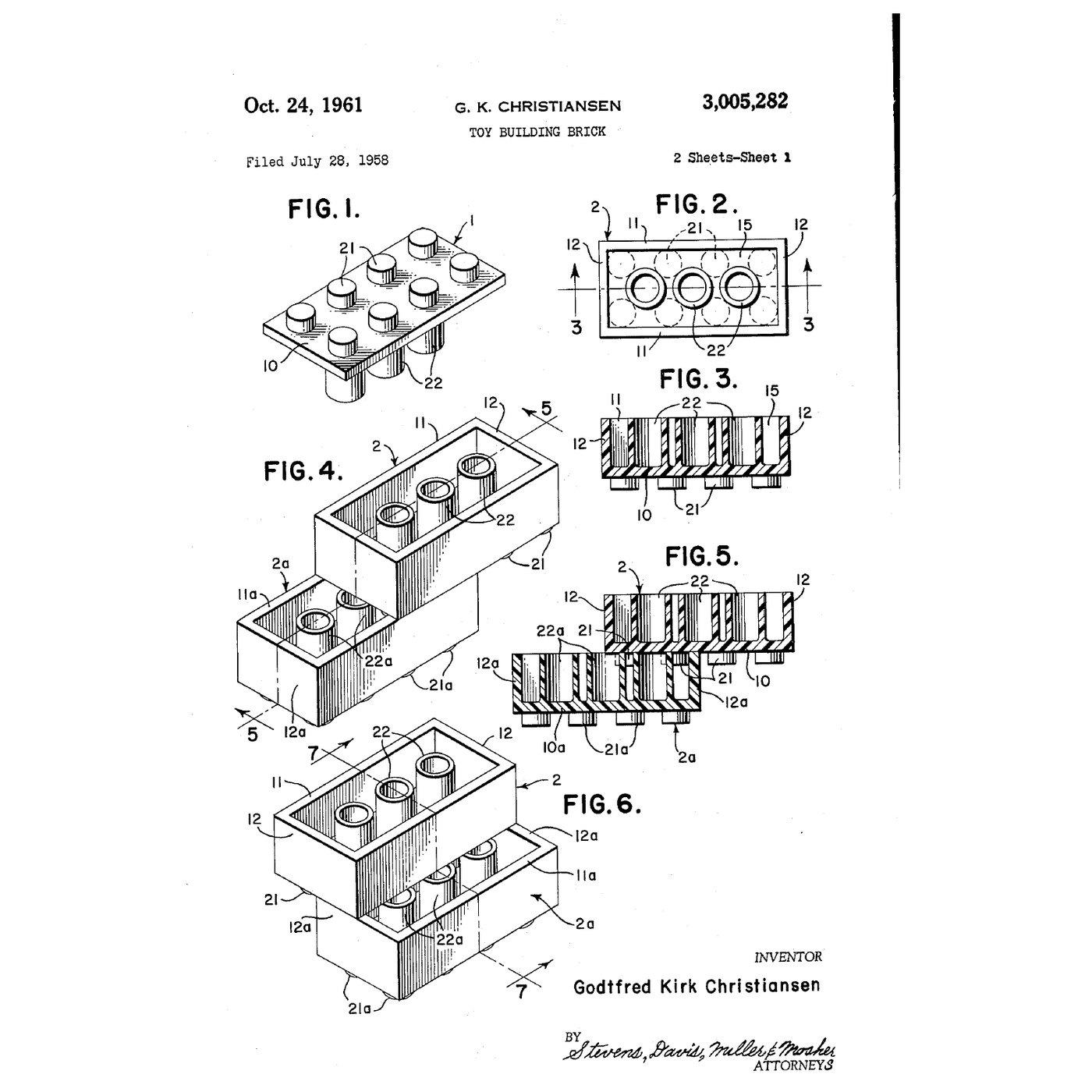
Godtfred Kirk Christiansen's 1958 patent solves it for the most-assembled object ever made. Bricks with studs on top had existed and did not hold together. The invention is what is **inside** the brick: secondary projections placed so that each one touches a stud and a side wall **tangentially** — line contact, not a wrapped interference fit.
This rung measures what an interference fit actually costs in force, finds out why the obvious full-contact version is unusable, and prints a test ladder to see how narrow the usable band really is.
Intermédiaire
About 4 hours, plus print time
Consignes
1
1
Read the claim, and look inside a brick
Read the claim, and look inside a brick
**US 3,005,282**, *Toy Building Brick*, **Godtfred Kirk Christiansen**; filed **28 July 1958** with Danish priority of **28 January 1958**, granted **24 October 1961**; 7 claims, US class 46-45. Expired. The drawing on this page is the patent's own sheet 1, and FIG. 1 and FIG. 3 are the whole invention.
The specification's own statement of purpose is *to provide improved coupling means for clamping* the bricks together, *thus providing for a vast variety of combinations*. Then it concedes the prior art plainly: bricks *provided with primary projections arranged in this manner are well-known per se*, and some had *internal projections located in the cavity*.
So what is new? The **geometry of the contact**. The claim requires that a *primary projection is tangent to at least one secondary projection and the inner face of at least one of the side walls* — and that the spacing is such that the secondary projections sit in the gaps between *the projected cross sections of four primary projections*.
Now pick up a brick and look inside. The studs on top are the primary projections. The tubes or ribs inside the underside are the secondary ones. Push two bricks together slowly and feel where the resistance comes from: not a stud sliding into a hole, but a stud being squeezed between a tube and a wall on **three narrow lines**.
Measure a stud and a tube with the micrometer, several of each, and write down the spread. The numbers are remarkable and step 4 explains why they have to be.
Outils nécessaires :
 Micromètre
 Pied à coulisse numérique 6 pouces
 Microscope numérique
2
2
Measure the clutch force, and then measure it again
Measure the clutch force, and then measure it again
Build a simple rig: clamp one brick in the vise, hook the spring scale to the brick above it, and pull straight up, slowly, until it releases. Read the peak.
Take ten readings on the same pair and write them all down. Then take ten on a different pair. Then ten on a pair you have already cycled a hundred times.
Three things to notice:
1. **The spread within one pair is small.** That is the point of the design.
2. **Cycling changes it very little.** Try a hundred more and measure again. This is the property the whole patent exists to deliver, and it is not obvious — most interference fits in plastic wear loose quickly.
3. **Orientation matters.** A pull straight up is not the same as a twist or a peel from one corner. Measure all three. The peel is far lower, which is exactly why you take bricks apart by tilting.
Then do the destructive version: warm a pair gently with the heat gun to about 60 °C, hold them together under load for ten minutes, cool, and measure again. That is **creep** — the polymer flowing under sustained stress — and it is the failure mode that kills most plastic interference fits over years. Note how little effect it has here, and hold that thought for step 4: low contact area and low strain are what makes a fit creep-resistant.
Outils nécessaires :
 Dynamomètre (peson à ressort)
 Étau d'établi
 Pistolet à air chaud
 Thermomètre infrarouge
 ChronomètreMicromètre
 Papier millimétré
 Lunettes de sécurité transparentes
 Cahier de laboratoire (avec copie)
3
3
Print an interference ladder and find your own window
Print an interference ladder and find your own window
Now make your own, so the tolerance argument stops being abstract.
Design a peg and a matching socket — a plain cylindrical peg 8 mm across, entering a socket in a 2 mm wall, engaged 5 mm deep. Print the peg once. Print the socket **seven times**, with nominal bore from 8.20 mm down to 7.80 mm in 0.05 mm steps.
Measure every printed bore with the calipers before you assemble anything, because a printer does not make what you asked for — it makes what it makes, and the *measured* interference is the variable, not the *commanded* one. This is the single most useful habit in the whole rung.
Assemble each pair and measure the pull-out force with the spring scale. Plot force against measured interference.
You will get three regions: a slack region where the force is near zero and the joint is useless; a working band; and a region where the socket splits on assembly or the peg refuses to enter. Mark the band on the plot and read off how wide it is in millimetres.
It will be narrow — a few hundredths — and that is the finding. Then compare it against what your printer can actually hold, which you measured at the start. If the usable band is narrower than your process spread, **the design is not manufacturable**, and no amount of care at assembly will fix it. That sentence is worth more than the plot.
Matériaux pour cette étape :
 Filament PLA1 pièce
 Filament ABS1 pièce
 Filament PETG1 pièce
Outils nécessaires :
 Imprimante 3DMicromètrePied à coulisse numérique 6 poucesDynamomètre (peson à ressort)Étau d'établi
 ÉbavureurPapier millimétréLunettes de sécurité transparentesCahier de laboratoire (avec copie)
4
4
Interference, pressure and why the contact is tangential
Interference, pressure and why the contact is tangential
Chargement du notebook Jupyter…
Outils nécessaires :
Papier millimétré5
5
History and context
History and context
**Attribution.** US 3,005,282, *Toy Building Brick*, Godtfred Kirk Christiansen; filed 28 July 1958, Danish priority 28 January 1958, granted 24 October 1961, expired. The drawing on this page is the patent's own.
**What was actually invented.** Stud-topped bricks were not new and the patent says so. What did not exist was a brick that **held**. Earlier versions relied on the stud entering the neighbouring brick's hollow with nothing to grip, so a model fell apart when lifted. The tubes and ribs inside the underside are the whole contribution, and the claim's insistence on *tangent* contact is the reason the grip is both strong enough to build with and weak enough for a child to undo.
**The tolerance story is the real one.** A fit like this only works if the parts are made to a few hundredths of a millimetre, every time, for decades — which means a stable polymer, a temperature-controlled tool and relentless measurement. The patent describes a geometry; delivering it is a manufacturing achievement, and step 3 is designed to make you feel exactly how small the window is.
**The idea to keep.** When an interference fit must survive repeated use, **reduce the contact area and let it flex**. A full cylindrical press fit is stiff, so a small error in size is a large error in force, and any wear or creep goes straight into slackness. Three narrow compliant lines absorb both. The same reasoning turns up in a spring-finger connector, a circlip and a collet.
**Honest limits.** Everything here is measured on printed parts, which are layered, anisotropic and nowhere near mould tolerance — step 3 is about the *shape* of the force-against-interference curve, not absolute numbers. The arithmetic in step 4 treats the wall as a thin elastic ring and ignores creep, temperature and the stud's own compliance; it is right about proportions and direction and should not be used to specify a part. And a real production fit is proved on measured samples over time, because creep is the failure that only shows up late.
Matériaux
3- 1 pièceEspace réservé
- 1 pièceEspace réservé
- 1 pièceEspace réservé
Outils requis
13- Espace réservé
- Espace réservé
- Espace réservé
- Espace réservé
- Espace réservé
- 1 vendor sell this, none ship to you yetEspace réservé
- Espace réservé
- Espace réservé
- Espace réservé
- Espace réservé
- Cahier de laboratoire (avec copie)10 % de commissionEspace réservé
- Espace réservé
- Espace réservé
Blueprints liés
Ces blueprints partagent des connaissances — techniques, matériaux ou principes


CC0 Domaine public
Ce blueprint est publié sous CC0. Vous êtes libre de copier, modifier, distribuer et utiliser ce travail pour tout usage, sans demander la permission.
Soutenez le Maker en achetant des produits via son Blueprint où il perçoit une Commission Maker définie par les Vendeurs, ou créez une nouvelle itération de ce Blueprint et incluez-le comme connexion dans votre propre Blueprint pour partager les revenus.