ART
BEAUTÉ ET BIEN-ÊTRE
ARTISANAT
CULTURE ET HISTOIRE
DIVERTISSEMENT
ENVIRONNEMENT
NOURRITURE ET BOISSONS
INGÉNIERIE INVERSE
SCIENCES
SPORTS
TECHNOLOGIE
TECHNOLOGIE PORTABLE
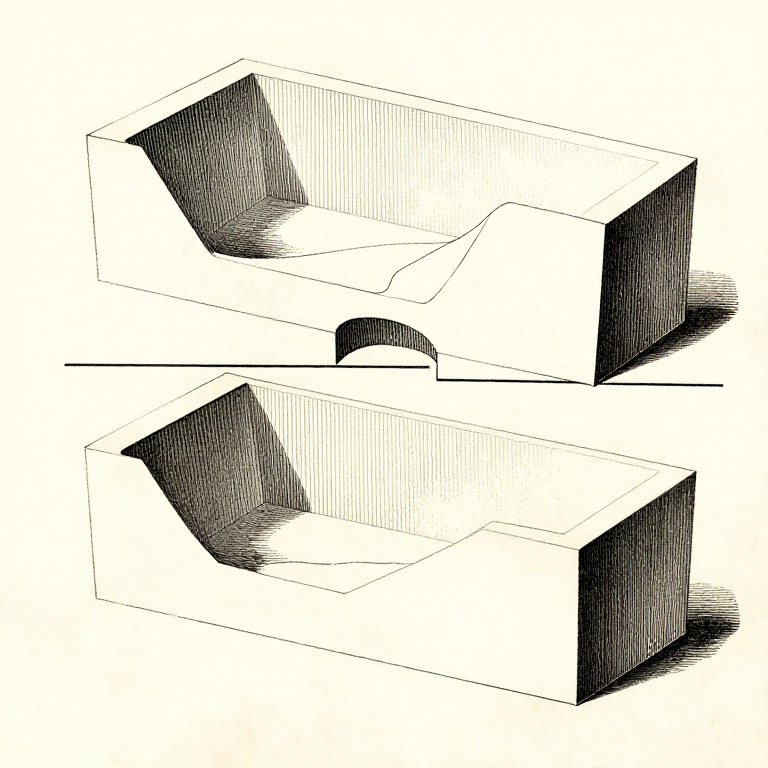


The Parting Line: Where the Mould Splits Decides Everything Else
A two-part mould has to come apart, so the pattern has to be able to leave both halves. Choosing where the split runs is the first real design decision in casting, and it constrains every decision after it.
Draft is measured FROM the parting line, so moving it changes which surfaces are tapered and in which direction. The gating usually enters at it. And the split always leaves a visible flash line on the finished part, so it also decides where the casting looks worst.
The rule that solves most cases: put the parting line at the LARGEST cross-section, so that both halves of the pattern taper away from it and neither has an undercut.
Avancé
3 hours
Consignes
1
1
Find the largest section and split there
Find the largest section and split there
Imagine drawing the pattern upward out of the drag and downward out of the cope. Any surface that overhangs — any UNDERCUT — makes that impossible, and the parting line must be placed so there are none.
At the widest cross-section, everything above tapers up and everything below tapers down, which is exactly the condition for a clean draw. That is why a sphere is parted at its equator and a cone at its base.
Where one parting line cannot avoid every undercut, the answers are a CORE, a loose piece in the pattern that stays behind and is removed separately, or a three-part mould. All three cost time, which is why the geometry is worth rearranging first.
Matériaux pour cette étape :
 Planche de bois dur1 pièce
Outils nécessaires :
 Pied à coulisse numérique 6 pouces
 Règle
Règle2
2
Cores make internal shapes, and they have to be held and vented
Cores make internal shapes, and they have to be held and vented
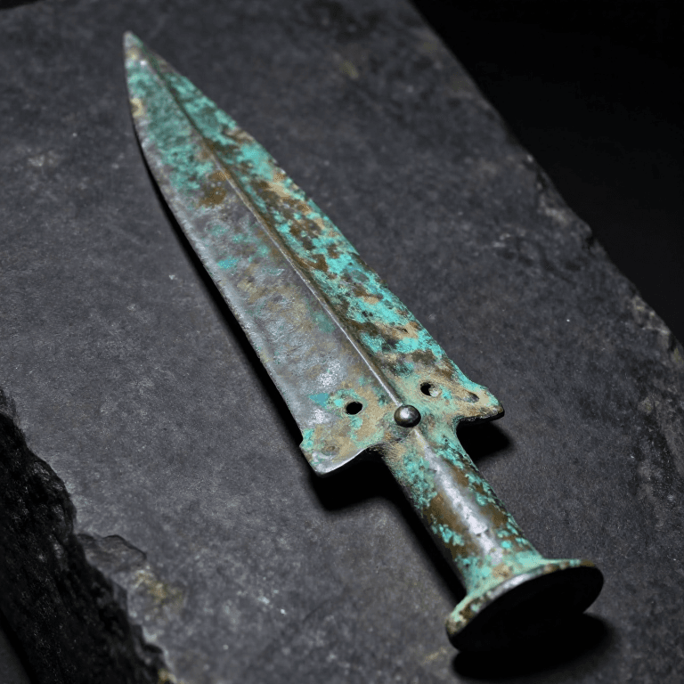
A CORE is a separate piece of bonded sand placed in the mould to make a hole or a hollow. The socket of a bronze spearhead, the inside of a kettle and the bore of a pipe are all cores.
It has to be LOCATED, by core prints — extensions on the pattern that leave sockets for the core's ends to sit in. A core that floats on molten metal moves, and a moved core gives a wall thick on one side and thin on the other.
It also has to VENT and to COLLAPSE. Gas generated inside a core has only one way out, through the core prints; and a core too strong to break down afterwards cannot be got out of the casting, which is why core binders are designed to lose strength at temperature.
Matériaux pour cette étape :
 Sable de moulage1 kg
 Argile de bentonite1 kg
Outils nécessaires :
 Châssis de moulage (chape et fond)Pied à coulisse numérique 6 pouces
 Loupe de bijoutier
3
3
Put the important surfaces in the drag
Put the important surfaces in the drag
Slag, dross and any sand washed loose float upward and collect at the top of the casting — which is the cope. So the surfaces that matter go in the DRAG, the lower half, where the metal is cleanest.
Thick sections also want to be high, because the feeding has to come from above: metal contracting as it freezes is fed by gravity from the riser, and a thick section at the bottom cannot be fed by one at the top.
Those two rules sometimes conflict, and then the decision is which matters more — a sound thick section or a clean visible surface. Recognising that it IS a conflict, rather than looking for a layout that satisfies both, is the useful step.
Matériaux pour cette étape :
Sable de moulage1 kgOutils nécessaires :
Châssis de moulage (chape et fond)Règle4
4
The flash line is permanent, so put it where it belongs
The flash line is permanent, so put it where it belongs
A thin fin of metal always forms where the two mould halves meet, however well they are clamped. It is ground off in fettling and it leaves a line that never quite disappears.
So put the parting line on an edge, a corner, or a face that will be machined — somewhere the line is expected — rather than across a visible curved surface where it will be obvious for ever.
And align the halves positively. Pins and sockets on the flask, or a moulded register, stop the cope shifting sideways relative to the drag. A shifted mould gives a casting with a visible step all the way round, and that one is not recoverable by fettling.
Matériaux pour cette étape :
Sable de moulage1 kgOutils nécessaires :
Châssis de moulage (chape et fond) Jeu de limesPied à coulisse numérique 6 pouces
Matériaux
3- 1 pièceEspace réservé
- 1 kgEspace réservé
- Espace réservé
Blueprints liés
Ces blueprints partagent des connaissances — techniques, matériaux ou principes
CC0 Domaine public
Ce blueprint est publié sous CC0. Vous êtes libre de copier, modifier, distribuer et utiliser ce travail pour tout usage, sans demander la permission.
Soutenez le Maker en achetant des produits via son Blueprint où il perçoit une Commission Maker définie par les Vendeurs, ou créez une nouvelle itération de ce Blueprint et incluez-le comme connexion dans votre propre Blueprint pour partager les revenus.