ART
BEAUTÉ ET BIEN-ÊTRE
ARTISANAT
CULTURE ET HISTOIRE
DIVERTISSEMENT
ENVIRONNEMENT
NOURRITURE ET BOISSONS
INGÉNIERIE INVERSE
SCIENCES
SPORTS
TECHNOLOGIE
TECHNOLOGIE PORTABLE

The Progressing-Cavity Pump: One Thread Fewer, and Nothing Is Squeezed
A single-start steel helix turns inside a rubber sleeve moulded as a two-start helix of twice the pitch. The two touch along a continuous sealing line, which divides the space between them into cavities. As the rotor turns, the cavities travel along the axis from suction to discharge — without ever changing size.
René Moineau worked out the geometry in 1930: two helical members, one with a single thread more than the other, with pitches in the same ratio. The result pumps an even, non-pulsing flow; primes itself; lifts sludge, paste, slurry, fruit pieces and crude oil that would clog or shred in any other pump; and does it gently, because nothing inside is ever compressed.
This rung prints a working pair — a rigid rotor and a flexible stator — works out the flow from the geometry and calibrates it.
Avancé
About 8 hours
Consignes
1
1
Read Moineau's rule off the patent
Read Moineau's rule off the patent
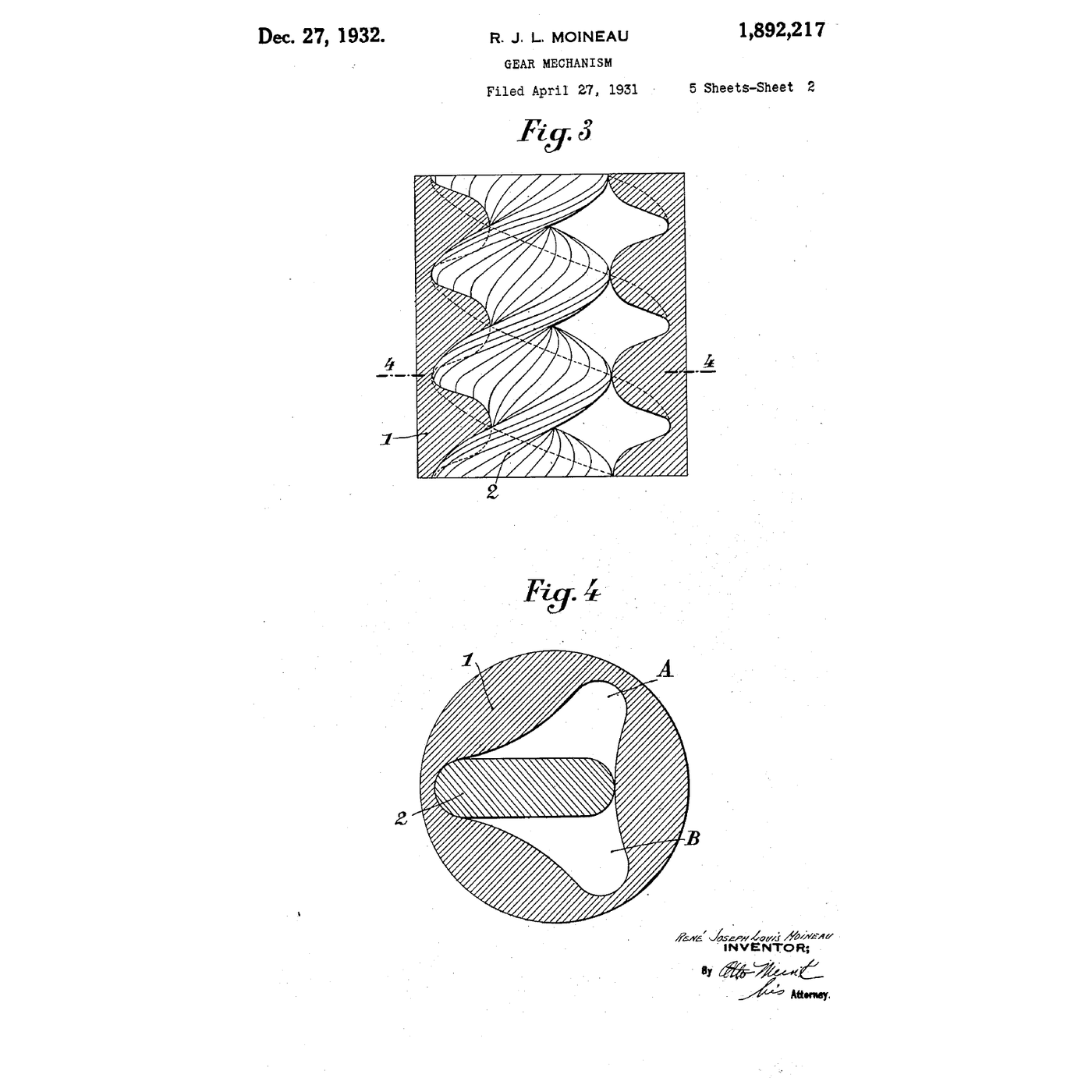
US 1,892,217 is titled 'Gear Mechanism', because Moineau saw it first as a pair of internal helical gears; the pump, the motor and the compressor are listed as uses. The rule is in the opening: two helical members *"having one helical thread or tooth more than"* the other, with *"the pitches of the helices of the two members"* in the same ratio as their numbers of threads, so that every thread of the inner member stays in contact with the outer one in every cross-section.
His figures show several combinations — two threads in three, three in four. The combination the world adopted is the simplest: **one thread inside two**, the stator's pitch twice the rotor's.
Note one thing the drawing makes plain: the inner member's axis is not fixed. It rolls round inside the outer one. Whatever drives it has to allow for that — step 4.
2
2
The cross-section: why nothing is squeezed
The cross-section: why nothing is squeezed
Chargement du notebook Jupyter…
3
3
Print a rigid rotor and a flexible stator
Print a rigid rotor and a flexible stator
Use the notebook's model numbers: rotor section 20 mm diameter, eccentricity 4 mm, rotor pitch 40 mm, stator pitch 80 mm, stator two pitches (160 mm) long.
- **Rotor:** in CAD, sweep a 20 mm circle offset 4 mm from the axis along a helix of 40 mm pitch, 180 mm long. Print it in PETG, upright, and sand it smooth — every ridge left by the printer is a leak path and a file on the stator.
- **Stator:** sweep the slot (20 mm wide, 36 mm long — 20 plus 4 × 4) along a two-start helix of 80 mm pitch, and subtract it from a 50 mm cylinder. Print it in **TPU** so it can grip the rotor, and model the slot 0.3 mm undersize so the rotor runs with a slight interference: that squeeze is the seal.
Push the stator into a length of PVC pipe as a housing and glue printed end fittings on, one with a side inlet for the suction and one with the discharge on the axis.
Matériaux pour cette étape :
 Filament PETG70 g
 Filament souple en TPU120 g
 Tube PVC1 pièce
 Assortiment de raccords PVC1 jeu
 Mastic silicone1 pièce
Outils nécessaires :
 Imprimante 3D à filament (FDM)
 Pied à coulisse numérique 6 pouces
 Assortiment de papier abrasif
 Coupe-tube
4
4
Drive a rotor whose axis moves
Drive a rotor whose axis moves
The rotor's axis orbits the stator's axis in a circle of radius e — 4 mm here — so it cannot be coupled rigidly to a motor. Production pumps use a coupling rod with a universal joint at each end, or a slender flexible shaft that bends to follow.
For a hand-driven model, a 60 mm length of reinforced hose clamped over both the drive shaft and the rotor's stub is enough: it bends to follow the orbit and transmits the modest torque. Support the drive shaft in two bearings in a printed bracket on the suction end, and seal it where it enters the housing with an O-ring.
Drive it slowly — under 200 rpm with the cordless drill. A progressing-cavity pump is a slow machine, and the notebook in step 6 shows why that is its strength.
Matériaux pour cette étape :
 Tuyau d'arrosage1 pièce
 Assortiment de colliers de serrage1 jeu
 Roulements de planche à roulettes2 pièces
 Barre d'acier brut1 pièce
 Assortiment de joints toriques1 kit
Outils nécessaires :
 Perceuse sans fil
 Jeu de clés Allen
 Clé à molette
 Tachymètre numérique
5
5
Pump water, then glycerine, and calibrate
Pump water, then glycerine, and calibrate
Wet the stator with water before the first turn — **never run it dry**. A dry rubber stator heats from friction and tears within seconds; the pumped liquid is its lubricant and its coolant.
Put the suction hose into a bucket of dyed water with the pump above it and turn the rotor. It primes itself: the travelling cavities pull the water up without any help. Count 20 turns into a measuring jug and divide. The notebook's figure for this geometry is 25.6 mL per turn; your pump will deliver a little less, the difference being what slips back past the sealing line.
Now raise the discharge hose higher and repeat: slip rises with pressure. Then pump glycerine, which is over a thousand times as viscous as water. The flow per turn barely changes — a thick liquid slips back less, not more. Try the same glycerine in the centrifugal pump from the first rung of this batch and it will barely move.
Matériaux pour cette étape :
 Eau5 litres
 Glycérine (végétale)1 litre
 Colorant alimentaire (traceur de visualisation d'écoulement)1 goutte
Outils nécessaires :
Perceuse sans filTachymètre numérique Verre doseur
 Seau
Seau Mètre ruban
6
6
Flow from geometry, and how gently it moves
Flow from geometry, and how gently it moves
Chargement du notebook Jupyter…
7
7
The flow has fallen away: find out why
The flow has fallen away: find out why
The usual reasons a progressing-cavity pump delivers less than its geometry says.
Flow
Loading...
8
8
History and context
History and context
**US 1,892,217, 'Gear Mechanism', René Joseph Louis Moineau of Paris; application filed 27 April 1931 (Serial 533,187), claiming a French filing of 13 May 1930; granted 27 December 1932.** Moineau was an aeronautical engineer; the specification treats the pair of helices generally, as a gear set usable as a pump, a motor or a compressor. He co-founded the company PCM to make the pump, and the principle is still widely called the Moineau pump.
Run backwards — liquid driven through it, turning the rotor — the same pair is a motor. That reversed form became the downhole mud motor that turns the drill bit in directional oil and gas drilling.
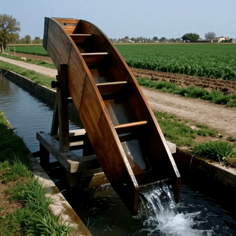
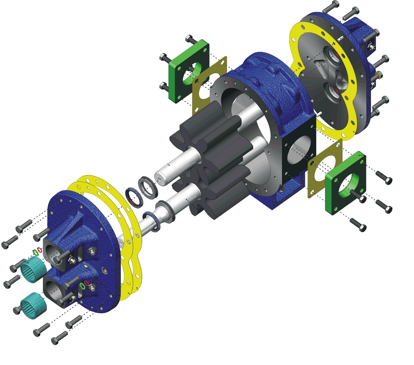
Its ancestors in this catalogue are the Archimedes screw (a helix that carries water along an axis, but open, so it cannot make pressure) and the gear pump (displacement by meshing members, but in pockets that are crushed at the mesh).
**Honest limits.** The stator wears, especially on abrasive slurries, and is replaced as a consumable. It must never run dry. The elastomer must suit the liquid — the wrong one swells and seizes the rotor, or hardens and leaks. The pump is long for its flow, and the coupling that follows the rotor's orbit is a wear part of its own.
Matériaux
13- 70 gEspace réservé
- Espace réservé
- 1 pièceEspace réservé
- Espace réservé
- 1 pièceEspace réservé
- Tuyau d'arrosage10 % de commission1 pièceEspace réservé
- Espace réservé
- Roulements de planche à roulettes10 % de commission2 piècesEspace réservé
- 1 pièceEspace réservé
- Espace réservé
- 5 litresEspace réservé
- 1 litreEspace réservé
- Espace réservé
Outils requis
11- Espace réservé
- Espace réservé
- Espace réservé
- Coupe-tube10 % de commissionEspace réservé
- 1 vendor sell this, none ship to you yetEspace réservé
- Espace réservé
- Espace réservé
- Espace réservé
- Espace réservé
- Espace réservé
- 1 vendor sell this, none ship to you yetEspace réservé
Blueprints liés
Ces blueprints partagent des connaissances — techniques, matériaux ou principes
Building an Archimedes' Screw — The Spiral Pump That Lifts Water Uphill
par Emma
Mécanique
61
0
0
0
2
0
Gear Pump
par Karen
TECHNOLOGIE
35
0
0
0
0
0
Vulcanizing Rubber with Sulfur — The Accidental Discovery That Put Tyres on the Road
par Charlie
Industriel
89
0
0
0
3
0
The Centrifugal Pump: Speed Squared, and Why It Cannot Lift Air
par Emma
Mécanique
12
0
0
0
0
0
The Peristaltic Pump: Two Places Closed at Once, and No Valve Touches the Fluid
par Emma
Mécanique
22
0
0
0
0
0
CC0 Domaine public
Ce blueprint est publié sous CC0. Vous êtes libre de copier, modifier, distribuer et utiliser ce travail pour tout usage, sans demander la permission.
Soutenez le Maker en achetant des produits via son Blueprint où il perçoit une Commission Maker définie par les Vendeurs, ou créez une nouvelle itération de ce Blueprint et incluez-le comme connexion dans votre propre Blueprint pour partager les revenus.