
ART
BEAUTÉ ET BIEN-ÊTRE
ARTISANAT
CULTURE ET HISTOIRE
DIVERTISSEMENT
ENVIRONNEMENT
NOURRITURE ET BOISSONS
INGÉNIERIE INVERSE
SCIENCES
SPORTS
TECHNOLOGIE
TECHNOLOGIE PORTABLE
The Scroll Compressor: Two Spirals, One Orbiting, No Valves
Emma

Créé par

Emma

27. septembre 2026SE
9
0
0
0
0

The Scroll Compressor: Two Spirals, One Orbiting, No Valves

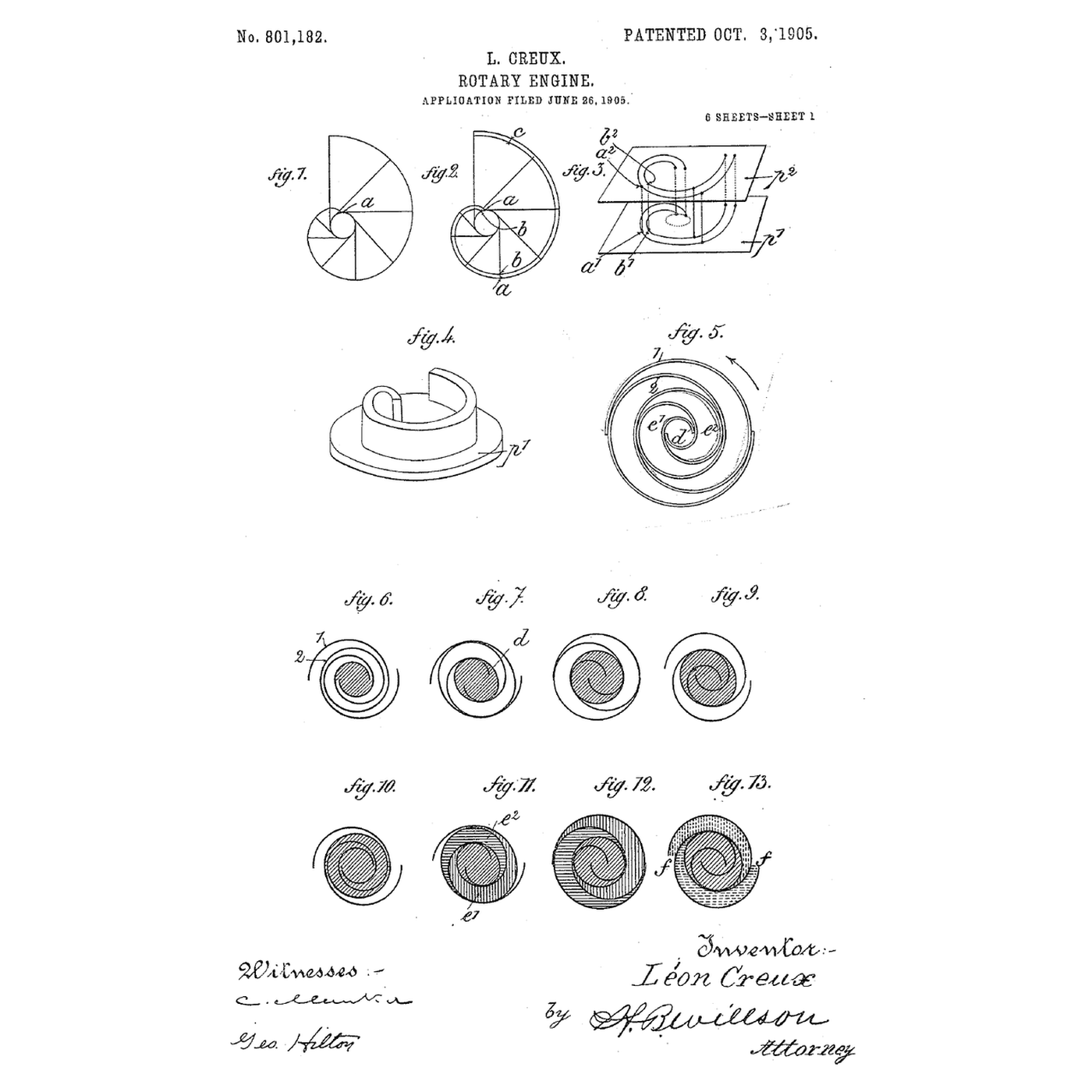
Two identical spiral walls, one fixed, one turned half a turn and moved round a small circle without ever rotating. Where they touch they seal off crescent-shaped pockets, and as the orbit goes round each pocket is carried inward and squeezed, until it opens into a port at the centre. Léon Creux patented it in 1905 as a steam engine — steam in at the centre, expanding outward — and noted in the same patent that it *"may of course be used also as a pump for compressing"*. It has no valves, no pistons changing direction and almost no vibration. It also demands walls cut to within microns, which is why it took the rest of the century to become practical. Today it is the compressor inside most household air conditioners and heat pumps. This rung generates the real involute geometry, prints a hand-cranked pair and shows why the tolerance matters more than anything else in the machine.
Avancé
About 8 hours

Consignes

1

Read Creux's drawing: a steam engine that runs backwards as a compressor

In US 801,182 the two *"spiral bands"* are engaged one inside the other. Steam is *"introduced at the center of the spirals"* and, as the moving band travels round, the sealed pockets carry it outward and let it expand, driving the shaft. In his words the steam *"will always operate at full pressure in the central chamber"*, expand *"at each revolution in the lateral chambers"*, and escape at the rim; his figures hatch the pockets three ways to show which is which. The bands have *"the shape of developed arc of a circle"* — the involute. The moving band does not rotate. Creux calls its motion a *"circular movement of translation"*: every point of it moves round an identical small circle, the way a hand polishing a table in circles keeps its fingers pointing the same way. Run it the other way — turn the shaft, feed gas at the rim — and the pockets travel inward and shrink. That is the compressor. Find on the drawing: the two bands; the central crank; the **bent shafts 12** running in the frame 13 through extensions of the plates, which *"only allow each"* plate *"to make a circular movement of translation the radius of which is equal to the radius of the cranks"* — the anti-rotation device; and the **segments 33 pressed by springs 34** that seal the edges. Step 4 copies the bent-shaft idea.
2

Generate the involute walls and watch the pockets form

Chargement du notebook Jupyter…
3

Print the fixed and orbiting scrolls

Use the notebook's numbers: pitch 12 mm, wall 2 mm, wall height 20 mm, three wraps, orbit radius 4 mm. Model each scroll as a wall standing on its own base plate, with the wall following the two involute curves (one for each face). Print them in PETG, wall upright, at the finest layer height your printer holds. The **fixed scroll**'s plate carries a 6 mm port at the centre and an inlet gap at the rim. The **orbiting scroll**'s plate carries a bearing boss on its back, on the scroll's centre. Offer them together, one wall inside the other, and check with a feeler gauge where they touch. Sand the wall tips flat on sandpaper laid on glass so each tip seals against the other plate. A printed pair will not be gas-tight — the step 6 notebook explains why — but it will move air.

Matériaux pour cette étape :

Filament PETGFilament PETG180 g

Outils nécessaires :

Imprimante 3D à filament (FDM)Imprimante 3D à filament (FDM)
Pied à coulisse numérique 6 poucesPied à coulisse numérique 6 pouces
Assortiment de papier abrasifAssortiment de papier abrasif
4

Orbit without rotating: the crank and the three anti-rotation cranks

Drive the orbiting scroll from a central crank: a shaft in a bearing through the base frame, carrying an eccentric pin offset exactly **4 mm** — the orbit radius — which runs in the bearing boss on the back of the orbiting plate. On its own that pin would let the orbiting scroll spin freely. Stop it with three small identical cranks at the corners of the plate, each also with a 4 mm throw, pivoted in the frame and pinned into the plate. Three equal parallel cranks can only let the plate translate: any point of it moves on a 4 mm circle and it cannot turn. (Production scrolls use a sliding cross-shaped Oldham ring for the same job; Creux used exactly these parallel cranks — his bent shafts 12.) Use skateboard bearings on the main crank and machine screws running in drilled holes for the three small cranks. Get the four throws equal with calipers; a crank 0.2 mm long binds the whole mechanism at one point of every turn.

Matériaux pour cette étape :

Roulements de planche à roulettesRoulements de planche à roulettes2 pièces
Barre d'acier brutBarre d'acier brut1 pièce
Vis à métauxVis à métaux12 pièces
Filament PETGFilament PETG60 g

Outils nécessaires :

Perceuse sans filPerceuse sans fil
Jeu de foretsJeu de forets
Pied à coulisse numérique 6 poucesPied à coulisse numérique 6 pouces
Jeu de clés AllenJeu de clés Allen
5

Turn it and measure what it delivers

Smear the wall tips with a thin film of silicone grease and assemble. Turn the crank slowly and watch through the inlet gap: the crescent pockets close off at the rim and walk inward, one wrap per turn. Push a length of clear vinyl tube onto the centre port and dip its other end 10 cm deep in a jug of water. Crank steadily: bubbles come out of the tube, so the pump is beating 10 cm of water — about 1 kPa. Lower the tube further until the bubbles stop; that depth is the most pressure your printed pair can hold against its own leakage. Now crank faster and repeat. The depth increases: leakage is a fixed rate through fixed gaps, so the faster the pockets move, the less time they spend leaking. That is why real scroll compressors run at motor speed.

Matériaux pour cette étape :

Tuyau vinyle transparentTuyau vinyle transparent1 mètre
EauEau1 litre

Outils nécessaires :

Verre doseurVerre doseur
RègleRègle
6

Built-in volume ratio, and why the tolerance is everything

Chargement du notebook Jupyter…
7

History and context

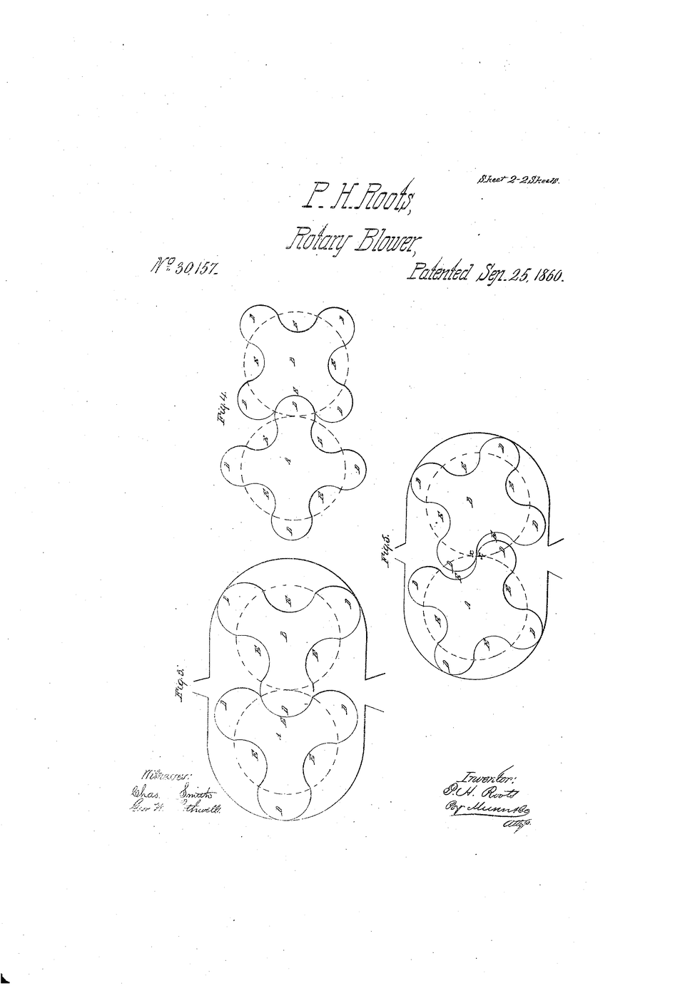
**US 801,182, 'Rotary Engine', Léon Creux, engineer, of 54 Rue Taitbout, Paris; filed 26 June 1905, granted 3 October 1905.** Creux presented it as a steam engine whose *"operation is soft and silent"*, and saw that it would also compress. It could not be made well. The walls must match the involute to within microns and the tips must seal against the opposite plate, and nothing in 1905 could cut a spiral to that accuracy in quantity. The idea stayed on paper for most of the century and became a production compressor only once numerically controlled machine tools could hold the tolerance. It then took over residential air conditioning and heat pumps, where its quietness and smoothness matter most. Its relatives in this catalogue are the other rotary displacement machines: the Roots blower (which does not compress internally at all), the rotary vane pump, and the gear pump. **Honest limits.** The built-in ratio is fixed, so a scroll working away from its design pressure ratio wastes work. It is limited in size: large flows need screws or centrifugals. It cannot swallow liquid — a slug of liquid in a pocket that is still shrinking has nowhere to go. And it is only ever as good as its machining.

Matériaux

6

Outils requis

8

CC0 Domaine public

Ce blueprint est publié sous CC0. Vous êtes libre de copier, modifier, distribuer et utiliser ce travail pour tout usage, sans demander la permission.

Soutenez le Maker en achetant des produits via son Blueprint où il perçoit une Commission Maker définie par les Vendeurs, ou créez une nouvelle itération de ce Blueprint et incluez-le comme connexion dans votre propre Blueprint pour partager les revenus.

Commentaires

(0)

Se connecter pour participer à la discussion

Chargement des commentaires...