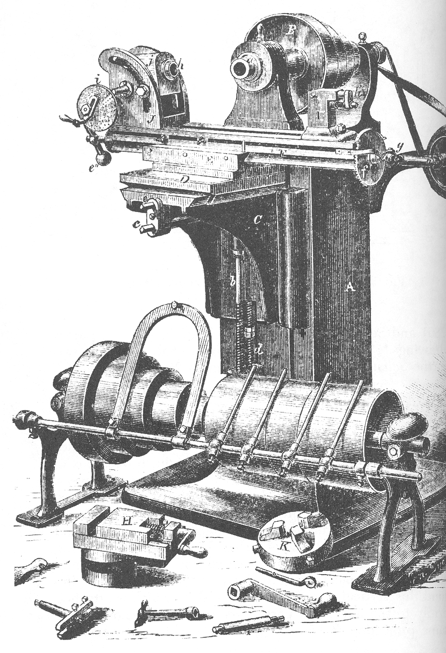


Universal Milling Machine
Consignes
Build the knee and column
Build the knee and column
Three axes, each on its own slideway, all square to each other.
- Build a column 350 mm tall from 18 mm ply, braced and square.
- Fit vertical ways of aluminium angle for the knee, using M6 × 50 hex bolts × 4, M6 flat washers × 8 and M6 hex nuts × 4.
- Make a knee that rides those ways, raised and lowered by an M8 screw — this is the Z axis.
- Check the knee stays square to the column through its full travel.
Squareness between axes is the whole accuracy of a milling machine. If the vertical way leans, every surface the machine cuts is out of square by the same amount, in a way no amount of careful working will correct. This is the point at which the planer and shaper earlier in this chain repay themselves: their flat, square surfaces are what makes an accurate machine frame possible at all.
Check squareness with the reversal method from the angle plate blueprint — measure, flip, measure again, and the divergence is twice the error.Matériaux pour cette étape :
 Contreplaqué de bouleau de Baltique1 feuille
 Cornière en aluminium2 pièces
 Rondelle plate8 pièces
 Écrou hexagonal4 pièces
Outils nécessaires :
 Scie sauteuse
 Perceuse sans fil
 Jeu de forets
 Équerre combinée
 Jeu de clés Allen
 Pied à coulisse numérique 6 pouces
Make the swivelling table — the universal part
Make the swivelling table — the universal part
This one joint is what the word universal refers to.
- Build a cross slide on the knee, driven by an M8 leadscrew — the Y axis.
- On top of it, fit a swivel plate pivoting about a central M8 bolt.
- Engrave or mark a degree scale around the swivel, readable to a degree.
- Mount the table on the swivel, with its own M8 leadscrew — the X axis.
- Clamp the swivel with two M6 × 40 hex bolts in curved slots, with M6 flat washers × 4.
Why swivelling the table cuts a helix. Feed the work straight past a rotating cutter and you get a straight slot. Swivel the table so the feed direction is at an angle to the cutter, connect the table's leadscrew to the dividing head so the work also rotates as it advances, and the cut traces a helix. That combination — linear feed geared to rotation — is how twist drill flutes, helical gears and worm threads are cut.
Mark the swivel scale carefully; the helix angle you can cut is set directly by it, and an error here appears as a drill that cuts undersize or a gear that meshes badly.Matériaux pour cette étape :
Contreplaqué de bouleau de Baltique1 feuille Plaque d'aluminium1 pièceRondelle plate8 piècesÉcrou hexagonal4 pièces
Outils nécessaires :
 Scie à chantournerPerceuse sans filJeu de forets
 PointeauÉquerre combinéePied à coulisse numérique 6 pouces
 Jeu de limes
Fit the horizontal arbor and overarm support
Fit the horizontal arbor and overarm support
A cutter on a long arbor deflects unless it is held at both ends.
- Mount a spindle in two 608 bearings in the column head, running horizontally.
- Fit an arbor of 16 mm aluminium round bar into the spindle, secured with a drawbar.
- Build an overarm from aluminium angle, projecting forward above the table.
- Fit a drop-down support bearing on the overarm to carry the arbor's outer end.
- Fix the overarm with M6 × 50 hex bolts × 2 and M6 flat washers × 4 so it can slide in and out.
The overarm is not optional. A cutter halfway along an unsupported arbor deflects under cutting load, so the slot comes out tapered and the finish chatters. Supporting the far end turns a cantilever into a beam supported at both ends, and the deflection falls dramatically. This is why a horizontal mill looks the way it does.
Slide the outer support as close to the cutter as the work allows. Every millimetre of unsupported arbor between cutter and bearing costs rigidity.Matériaux pour cette étape :
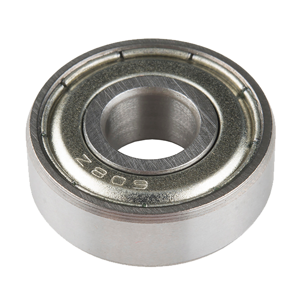 Ball Bearing - Non-Flanged (8mm Bore, 22mm OD)3 pièces
 Rond en aluminium1 pièceCornière en aluminium1 pièceRondelle plate4 piècesÉcrou hexagonal2 pièces
Outils nécessaires :
Perceuse sans filJeu de forets Monture de scie à métaux avec lamesJeu de clés AllenJeu de limesPied à coulisse numérique 6 pouces
Mount the dividing head and cut a helical groove
Mount the dividing head and cut a helical groove
The two machines working together — which is the point of the whole chain.
- Bolt the dividing head from batch 69 onto the table.
- Gear its input to the table leadscrew so the work rotates as the table advances.
- Swivel the table to the helix angle you want.
- Take a light cut along a round workpiece and observe the groove produced.
- Index the dividing head one division and cut again.
Matériaux pour cette étape :
Rond en aluminium1 pièceRondelle plate4 piècesÉcrou hexagonal4 piècesOutils nécessaires :
Jeu de clés AllenPied à coulisse numérique 6 poucesÉquerre combinéePerceuse sans filWhy milling won, and history
Why milling won, and history
Joseph R. Brown of Brown & Sharpe built the first universal milling machine in 1862. The company's account is specific about the motive: a contract for twist drills whose flutes were being formed by hand, slowly and inconsistently. The machine was built to make a better tool, and it ended up remaking the workshop.
The arithmetic of why milling displaced planing and shaping. A shaper's single tool cuts on the forward stroke only — call it half the time, one tooth. A milling cutter with sixteen teeth at moderate speed has several teeth in the cut continuously. The metal removal rate is not slightly better, it is several times better, and it improves further with every advance in cutter material. Taylor-White high-speed steel in 1900 and cemented carbide in the 1920s, both already in this catalogue, multiplied milling's advantage while doing far less for the shaper.
The dependency is worth stating plainly: this machine needs the dividing head to do its most valuable work. A mill without accurate angular division can cut slots and faces; with it, the same machine cuts gears, splines, ratchets, reamer flutes and drills. That is why batch 69's dividing head had to come before this blueprint in the chain rather than after.
What it led to: the vertical mill, the jig borer at the end of this batch, and eventually the machining centre with an automatic tool changer — which is a milling machine that has borrowed the turret lathe's indexed tooling. The two lines of descent in this batch converge.
Matériaux
7- 1 feuilleEspace réservé
- 3 piècesEspace réservé
- 24 piècesEspace réservé
- 14 piècesEspace réservé
- 1 pièceEspace réservé
- Ball Bearing - Non-Flanged (8mm Bore, 22mm OD)10 % de commission3 pièces€1.12
- 1 pièceEspace réservé
Outils requis
10- 1 vendor sell this, none ship to you yetEspace réservé
- 1 vendor sell this, none ship to you yetEspace réservé
- Espace réservé
- Espace réservé
- Espace réservé
- Espace réservé
- Espace réservé
- Espace réservé
- Espace réservé
- Espace réservé
Blueprints liés
Ces blueprints partagent des connaissances — techniques, matériaux ou principes

CC0 Domaine public
Ce blueprint est publié sous CC0. Vous êtes libre de copier, modifier, distribuer et utiliser ce travail pour tout usage, sans demander la permission.
Soutenez le Maker en achetant des produits via son Blueprint où il perçoit une Commission Maker définie par les Vendeurs, ou créez une nouvelle itération de ce Blueprint et incluez-le comme connexion dans votre propre Blueprint pour partager les revenus.