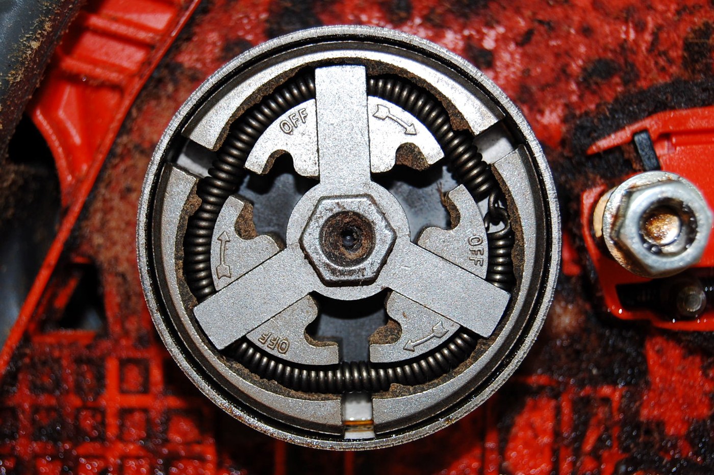


Centrifugal Clutch
Instruksi
Build the drum and hub
Build the drum and hub
A shallow drum, and a hub that spins inside it.
- Cut a drum from 18 mm ply: a 120 mm disc with a 100 mm internal bore, leaving a 10 mm rim.
- Line the bore with a strip of 1 mm aluminium as the friction surface.
- Cut a 70 mm hub disc from 18 mm ply and bore it 8.0 mm.
- Mount drum and hub on separate 608 bearings so each turns independently on the same axis.
Coaxial and independent is the requirement. The whole point is that at low speed the input hub spins freely inside a stationary drum — so any rubbing at rest, from a wonky bore or a tight bearing, masks the very behaviour you are building.
Spin the hub with the drum held: it should coast for several seconds. If it stops quickly, find the drag before adding the shoes.Material untuk langkah ini:
 Kayu Lapis Birch Baltik1 lembar
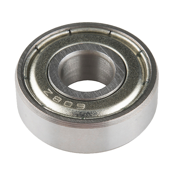 Ball Bearing - Non-Flanged (8mm Bore, 22mm OD)3 buah
 Batang Rata Aluminium1 buah
Alat yang dibutuhkan:
 Gergaji Ukir Listrik
 Gergaji Coping
 Bor Tanpa Kabel
 Set Mata Bor
 Set Kikir
 Jangka Sorong Digital 6 Inci
Make two pivoting shoes
Make two pivoting shoes
Two, opposite each other, so the assembly stays balanced.
- Cut two shoes from 6 mm aluminium, each a curved segment matching the drum bore radius.
- Drill a pivot hole near one end of each.
- Pivot them to the hub 180 degrees apart with M5 × 20 socket head cap screws × 2, M5 flat washers × 4 and M5 nylon insert lock nuts × 2.
- Check each shoe swings out freely and its outer face meets the drum squarely.
- Weigh both shoes — they must match within a gram or two.
Balance is not optional at speed. Two shoes of unequal mass make the whole assembly vibrate, and vibration at several thousand revolutions per minute in a plywood model is a genuine hazard rather than an annoyance. If one shoe is heavier, file material from its non-contact edge until they match.
Pivoted shoes rather than sliding weights because a pivot has almost no friction to overcome, so engagement speed is set by the spring rather than by stiction — which makes the measurement in step 4 repeatable.Material untuk langkah ini:
Batang Rata Aluminium1 buah Ring Rata4 buah
 Mur Pengunci Sisipan Nilon2 buah
Alat yang dibutuhkan:
Gergaji CopingSet KikirBor Tanpa KabelSet Mata Bor Set Kunci L (Hex)Jangka Sorong Digital 6 Inci
Fit the return springs — the tuning element
Fit the return springs — the tuning element
The spring alone sets the engagement speed.
- Hook a light spring between the two shoes, or one spring per shoe back to the hub.
- Set the tension so the shoes sit clear of the drum at rest with about 1 mm clearance.
- Note which spring you fitted, and keep the spares.
- Confirm both shoes lift off together — unequal springs engage one shoe first, which is the same imbalance problem again.
The physics you are tuning against. Centrifugal force rises with the square of speed while the spring force rises only linearly with extension. Those two curves cross at exactly one speed, and that crossing IS the engagement point. Because one is quadratic, engagement is quite sharp — a small speed increase past the crossing produces a large net outward force.
Keep the spare springs. Step 4 asks you to swap them, and the change in engagement speed is the most instructive measurement in the build.Material untuk langkah ini:
 Set Pegas Tekan1 set
Alat yang dibutuhkan:
Set Kunci L (Hex)Jangka Sorong Digital 6 InciSet KikirFind the engagement speed, then change it
Find the engagement speed, then change it
Measure the crossing point, then move it deliberately.
- Drive the hub with a variable-speed drill and hold the drum lightly.
- Raise speed slowly until the drum begins to be dragged round. Record that speed.
- Reduce speed until it releases — note that this happens LOWER than engagement.
- Swap to a stiffer spring and repeat both readings.
- Tabulate spring versus engage and release speeds.
Alat yang dibutuhkan:
Bor Tanpa Kabel StopwatchJangka Sorong Digital 6 Inci
Where it wins, and history
Where it wins, and history
What it buys is the removal of the operator. No lever, no linkage, no pedal, no decision. A small engine can idle without stalling and without driving anything, then take up drive smoothly as it is revved. That is why chainsaws, strimmers, go-karts, mopeds and countless small machines use one — most of them have no clutch control at all, and their users never think about it.
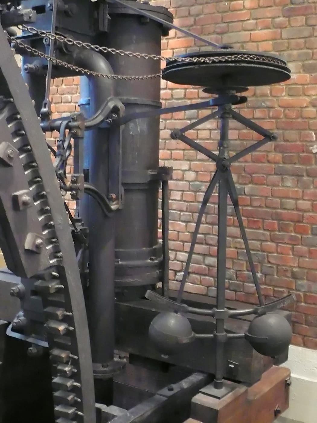
The same principle, two different jobs. The centrifugal governor already in this catalogue uses flying weights to REGULATE speed by throttling the input. This uses them to CONNECT drive. Identical physics, opposite purpose — one feeds back to reduce speed, the other engages a load. Recognising that a mechanism is a physical principle rather than a fixed device is how you find new uses for it.
Its honest limits: it engages at only one speed, set when it was built, so it cannot be used deliberately at other speeds. It slips every time it engages, and that slip is heat and wear — a chainsaw clutch is a consumable. It cannot hold a load stationary. And it cannot be disengaged at speed at all, which is why machines using one still need a separate brake.
Against the batch: cone clutch — any speed, needs an operator, slips under overload. Dog clutch — no slip ever, needs matched speeds. Centrifugal — no operator, one speed only. Three answers to "connect these shafts", and the choice is really a question about who or what decides when.
Bahan
6- 1 lembarPlaceholder
- 3 buah$1.26
- 1 buahPlaceholder
- 4 buahPlaceholder
- Placeholder
- 1 setPlaceholder
Alat yang Diperlukan
8- 1 vendor sell this, none ship to you yetPlaceholder
- Placeholder
- 1 vendor sell this, none ship to you yetPlaceholder
- Placeholder
- Placeholder
- Placeholder
- Placeholder
- Placeholder
Blueprint terkait
Blueprint ini berbagi pengetahuan — teknik, bahan, atau prinsip

CC0 Domain Publik
Cetak biru ini dirilis di bawah CC0. Anda bebas untuk menyalin, memodifikasi, mendistribusikan, dan menggunakan karya ini untuk tujuan apa pun, termasuk komersial, tanpa meminta izin.
Dukung Maker dengan membeli produk melalui Cetak Biru mereka di mana mereka mendapatkan Komisi Pembuat yang ditetapkan oleh Penjual, atau buat iterasi baru dari Cetak Biru ini dan masukkan sebagai koneksi di milik Anda sendiri.