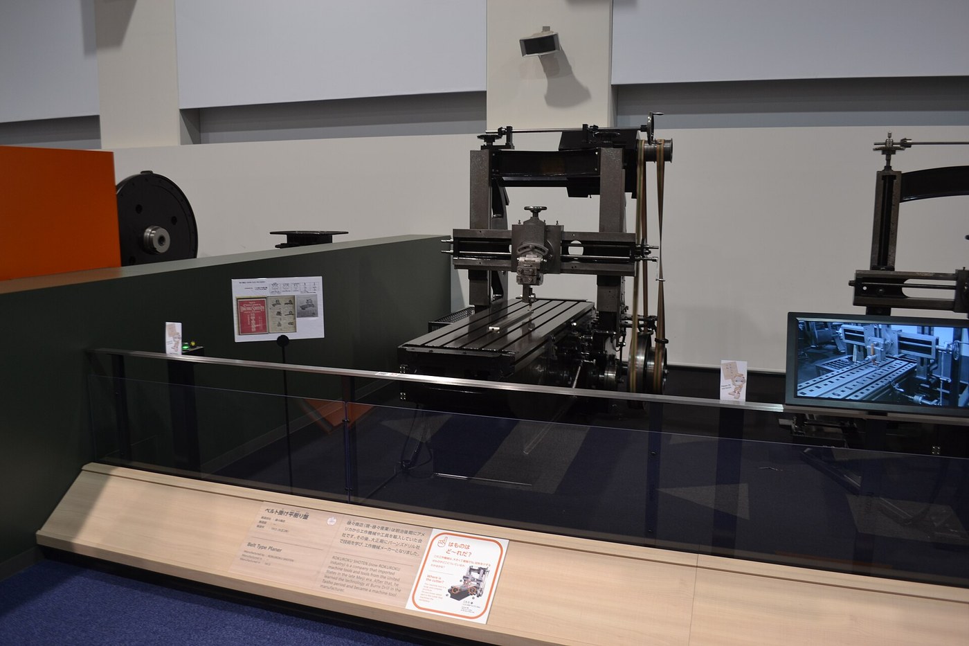


Metal Planing Machine
Instruksi
Build the bed and its slideway
Build the bed and its slideway
The machine can only be as straight as this one component.
- Cut a bed 500 × 180 mm from 18 mm Baltic birch plywood.
- Fix two lengths of aluminium angle along it as vee-ways, 120 mm apart, with M5 × 30 socket head cap screws × 8, M5 flat washers × 16 and M5 hex nuts × 8.
- Before final tightening, sight along both ways and shim until each is straight.
- Check the two ways are parallel at three points along the length with the caliper.
What the earlier work made possible. Roberts and Clement had no straight reference to build from except hand-scraped surface plates made by the three-plate method. Every planer bed was scraped flat by hand first; the machine then produced flat surfaces faster and more repeatably than the hand process that created it. That bootstrap — hand accuracy used once to build a machine that outperforms it — is the central event in machine tool history.
Sight along the ways with your eye at bed level before trusting any measurement. The eye detects a bow of a few tenths of a millimetre over half a metre far better than a short caliper can.Material untuk langkah ini:
 Kayu Lapis Birch Baltik1 lembar
 Siku aluminium2 buah
 Ring Rata16 buah
 Mur Segi Enam8 buah
Alat yang dibutuhkan:
 Gergaji Ukir Listrik
 Bor Tanpa Kabel
 Set Mata Bor
 Set Kunci L (Hex)
 Siku Kombinasi
 Jangka Sorong Digital 6 Inci
Make the reciprocating table
Make the reciprocating table
The work moves; the tool stands still. That is what distinguishes a planer.
- Cut a table 300 × 150 mm from 18 mm ply and face its top with 6 mm aluminium plate.
- Fit matching vee-runners underneath to ride the bed's ways.
- Cut two T-slots or a row of clearance holes in the table top for work clamps.
- Fit the table and check it slides the full length with even resistance.
Why the work reciprocates rather than the tool. For long or heavy work, moving the table means the cutting tool and its heavy support stay put, and only the workpiece and table carry the reversing loads. The opposite choice — fixed work, moving tool — is the shaping machine, and the crossover point is roughly the size of the work, which is exactly the distinction the next blueprint in this chain explores.
Even resistance along the whole travel is the test. A tight spot means the ways are not parallel, and the tool will cut deeper there, producing exactly the unflatness the machine exists to remove.Material untuk langkah ini:
Kayu Lapis Birch Baltik1 lembar Pelat Aluminium1 buahSiku aluminium1 buahRing Rata8 buahMur Segi Enam4 buah
Alat yang dibutuhkan:
Gergaji Ukir ListrikBor Tanpa KabelSet Mata Bor Set KikirSet Kunci L (Hex)Jangka Sorong Digital 6 Inci
Build the cross rail and tool post with a clapper box
Build the cross rail and tool post with a clapper box
The tool must cut one way and lift clear on the return.
- Bridge the bed with a cross rail of aluminium angle on two uprights, fixed with M6 × 50 hex bolts × 4, M6 flat washers × 8 and M6 hex nuts × 4.
- Make a tool slide that can be moved along the rail and locked.
- Hinge the tool holder at its top so it can swing freely BACKWARD only — this is the clapper box.
- Fit a stop so it cannot swing forward past vertical.
- Clamp a lathe tool or a ground HSS blank in the holder.
The clapper box is the detail that makes planing work. On the cutting stroke the tool is pushed against its stop and cuts. On the return the same friction lifts the hinged holder and the tool skids harmlessly over the surface. Without it the tool digs in on the return and either scores the finished surface or breaks.
Test the clapper by dragging the tool backward by hand — it should lift immediately and drop back cleanly. A stiff hinge is worse than no hinge, because it lifts late, after it has already scratched.Material untuk langkah ini:
Siku aluminium1 buah Batang Rata Aluminium1 buahRing Rata8 buahMur Segi Enam4 buah
 Sekrup Kepala Soket4 buah
 Mur Pengunci Sisipan Nilon2 buah
Alat yang dibutuhkan:
 Rangka Gergaji Besi dengan BilahBor Tanpa KabelSet Mata BorSet Kunci L (Hex)Set KikirSiku Kombinasi
Add the indexing feed and cut a surface
Add the indexing feed and cut a surface
One pass cuts a groove. A surface needs a controlled sideways step between passes.
- Fit a leadscrew of M8 threaded rod across the cross rail, driving the tool slide.
- Fit a handwheel marked in divisions so a known feed can be dialled in.
- Set a cut of about 0.3 mm depth in a soft aluminium or hardwood workpiece.
- Plane the length, index the tool across by 1 mm, and repeat until the whole face is cut.
- Check the finished surface against a straightedge in both directions.
Material untuk langkah ini:
Batang Rata Aluminium1 buahRing Rata4 buahMur Segi Enam4 buahAlat yang dibutuhkan:
Bor Tanpa KabelSet Mata BorJangka Sorong Digital 6 InciSiku KombinasiSet Kunci L (Hex)Set KikirWhat it made possible, and history
What it made possible, and history
Richard Roberts built a planing machine in Manchester around 1817, and Joseph Clement built one in London in the same period; several others followed within a few years, which is usually the sign of a problem everyone was pushing at rather than a single flash of insight. The problem was that steam engines needed flat, square, parallel surfaces in quantity — valve faces, slide bars, machine beds — and hand scraping could not supply them.
The bootstrap is the important part. The first planers were built on surfaces made by the hand three-plate method. Those planers then produced flatter, more consistent surfaces than hand work could, and those surfaces became the beds of the next generation of machines, which were better again. Machine tool accuracy compounds: each generation is built by the one before it. This is the single clearest example of that ratchet in the whole history of manufacturing.
What it enabled downstream, in this batch and beyond: the shaping machine is the planer's small-work counterpart and follows it by two decades. Flat, accurate machine beds made the turret lathe and the milling machine possible. And the flat ways produced by planing are what every slideway in every later machine tool depends on.
Its honest limits: a planer is slow — it cuts in one direction only and wastes the return stroke, which is precisely the problem the Whitworth quick-return mechanism was invented to reduce. It needs floor space proportional to the work length. And it has been largely displaced by milling, which cuts continuously with a rotating cutter rather than intermittently with a single point. Large planers survive for very long work like machine beds, where a mill would need an impractically long travel.
Alat yang dibutuhkan:
Jangka Sorong Digital 6 InciBahan
8- 1 lembarPlaceholder
- 4 buahPlaceholder
- 36 buahPlaceholder
- 20 buahPlaceholder
- 1 buahPlaceholder
- 1 buahPlaceholder
- 4 buahPlaceholder
- Placeholder
Alat yang Diperlukan
8- 1 vendor sell this, none ship to you yetPlaceholder
- 1 vendor sell this, none ship to you yetPlaceholder
- Placeholder
- Placeholder
- Placeholder
- Placeholder
- Placeholder
- Placeholder
Blueprint terkait
Blueprint ini berbagi pengetahuan — teknik, bahan, atau prinsip


CC0 Domain Publik
Cetak biru ini dirilis di bawah CC0. Anda bebas untuk menyalin, memodifikasi, mendistribusikan, dan menggunakan karya ini untuk tujuan apa pun, termasuk komersial, tanpa meminta izin.
Dukung Maker dengan membeli produk melalui Cetak Biru mereka di mana mereka mendapatkan Komisi Pembuat yang ditetapkan oleh Penjual, atau buat iterasi baru dari Cetak Biru ini dan masukkan sebagai koneksi di milik Anda sendiri.