SENI
KECANTIKAN & KESEHATAN
KERAJINAN
BUDAYA & SEJARAH
HIBURAN
LINGKUNGAN
MAKANAN & MINUMAN
REKAYASA BALIK
ILMU PENGETAHUAN
OLAHRAGA
TEKNOLOGI
PERANGKAT PAKAI
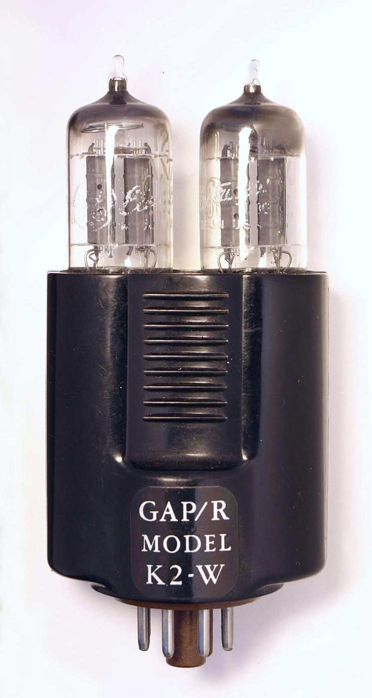


The Operational Amplifier
The name is literal. John Ragazzini and his colleagues at Columbia coined it in a paper of May 1947 about wartime work on gun directors, and the amplifiers in question were called operational because they performed mathematical OPERATIONS - adding, scaling, integrating, differentiating - inside a machine that solved the differential equations of a shell in flight while the shell was still in the gun.
The circuit is Black's feedback amplifier with the loop closed by two impedances instead of two resistors, and the argument for it needs no electronics at all. Give the amplifier enormous gain and an inverting input. For the output to sit anywhere sensible, that input must be within microvolts of zero, so no current goes into the amplifier and whatever arrives through the input resistor has to leave through the feedback element. That is Kirchhoff, and it means the answer is a ratio of two components. Put a capacitor in the feedback path and the same argument gives you an integral.
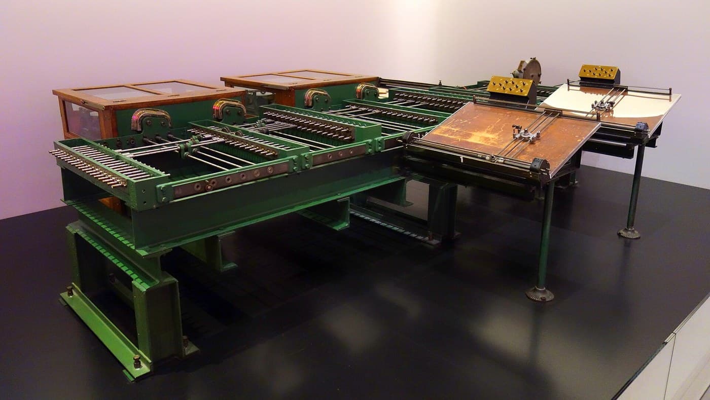
It is the same integral the wheel-and-disc machine performed with friction sixteen years earlier, and it wins for a reason that has nothing to do with accuracy: both are good to about a tenth of a per cent, and one takes a day of gearing to set up while the other takes a few minutes of patch cords.
It loses on one column, and that is worth knowing. A friction wheel parked at a radius stays there all day; a charged capacitor leaks, and the amplifier's own offset voltage and bias current are integrated along with the signal. A general-purpose bipolar op-amp integrating onto a microfarad will hit the supply rail in under two minutes with no input at all. That is why every analogue computer has a reset button and no differential analyser ever needed one.
Menengah
3 hours
Instruksi
1
1
Two resistors decide everything
Two resistors decide everything
Wire a TL072 as an inverting amplifier, 1k in and 100k back, on a split supply. Feed it 100 mV at 1 kHz and check the output is 10 V peak and upside down.
Now measure the voltage at the summing junction itself with the scope on its most sensitive range. It barely moves - a few hundred microvolts while the output swings twenty. That stillness is the entire circuit.
Material untuk langkah ini:
 Op-amp JFET TL0721 bungkus
 Kit Resistor 1/4 W1 kit
 Set Kapasitor Keramik1 kit
Alat yang dibutuhkan:
 Breadboard - Classic
 Pembangkit Sinyal DDS
 Osiloskop Digital
 Catu Daya Meja
2
2
Integrate, and watch it walk away
Integrate, and watch it walk away
Swap the feedback resistor for a 1 uF capacitor and feed the input a square wave: the output is a triangle, which is the integral.
Now disconnect the input entirely and watch the output with a stopwatch. It ramps away to a rail with nothing applied. Time it, and you have measured the amplifier's offset and bias current with two components and a clock.
Material untuk langkah ini:
 Kit kapasitor elektrolit1 kitKit Resistor 1/4 W1 kit
Alat yang dibutuhkan:
Op-amp JFET TL072 Penguat operasional LM741Osiloskop Digital
 StopwatchBreadboard - Classic
3
3
Virtual earth, integrator drift, and four integrators
Virtual earth, integrator drift, and four integrators
Memuat notebook Jupyter…
Alat yang dibutuhkan:
 Komputer Desktop
4
4
Compendium: why it needs a capacitor inside it
Compendium: why it needs a capacitor inside it
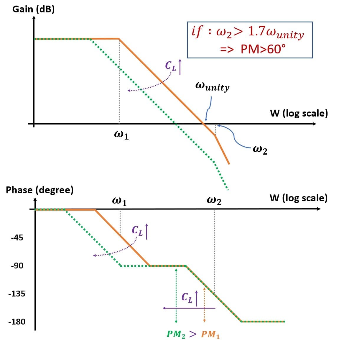
An amplifier with a hundred decibels of gain and three internal stages has three lags, and by Bode's rule those give it a slope of sixty decibels per decade well before the gain reaches unity. Close a unity-gain loop round that and it oscillates - which is exactly what the earliest monolithic op-amps did, and why they shipped with a table of external compensation capacitors and a warning about which gains were safe. The 741 of 1968 put a single 30 pF capacitor on the chip to create one dominant pole at about 10 Hz, so the gain falls at twenty decibels per decade all the way to unity and the part is stable at any gain, straight out of the tube. It is the second row of blueprint 8's table, cast in silicon and sold ten million times.
The bill arrives as a specification everybody quotes without noticing what it is. Gain times bandwidth is constant on a twenty-decibel-per-decade slope, so a 1 MHz part gives a hundred times of gain out to 10 kHz and ten times out to 100 kHz - and that is not a limitation of the transistors, it is the compensation capacitor doing precisely the job it was put there for. Slew rate is the same capacitor seen from the other side: the internal stage can only charge it so fast, so a large fast signal stops obeying the small-signal bandwidth entirely and the output goes into a straight-line ramp.
Bahan
4- 1 bungkusPlaceholder
- 1 kitPlaceholder
- Placeholder
- Placeholder
Alat yang Diperlukan
8- Breadboard - Classickomisi 10%$9.50
- Placeholder
- Osiloskop Digitalkomisi 10%Magento Legacy Storeships internationallyPlaceholder
- Placeholder
- Placeholder
- Placeholder
- Placeholder
- Placeholder
Blueprint terkait
Blueprint ini berbagi pengetahuan — teknik, bahan, atau prinsip


CC0 Domain Publik
Cetak biru ini dirilis di bawah CC0. Anda bebas untuk menyalin, memodifikasi, mendistribusikan, dan menggunakan karya ini untuk tujuan apa pun, termasuk komersial, tanpa meminta izin.
Dukung Maker dengan membeli produk melalui Cetak Biru mereka di mana mereka mendapatkan Komisi Pembuat yang ditetapkan oleh Penjual, atau buat iterasi baru dari Cetak Biru ini dan masukkan sebagai koneksi di milik Anda sendiri.