SENI
KECANTIKAN & KESEHATAN
KERAJINAN
BUDAYA & SEJARAH
HIBURAN
LINGKUNGAN
MAKANAN & MINUMAN
REKAYASA BALIK
ILMU PENGETAHUAN
OLAHRAGA
TEKNOLOGI
PERANGKAT PAKAI


The Synchronous Clock: Telling Time by the Power Station's Cycles
Every electric clock needs something regular to count. Henry E. Warren of Ashland, Massachusetts, saw that an alternating-current supply already carries one: the alternations of the generators. A small motor that turns exactly in step with them, geared down to hands, keeps time — provided the power station keeps its total count of alternations right.
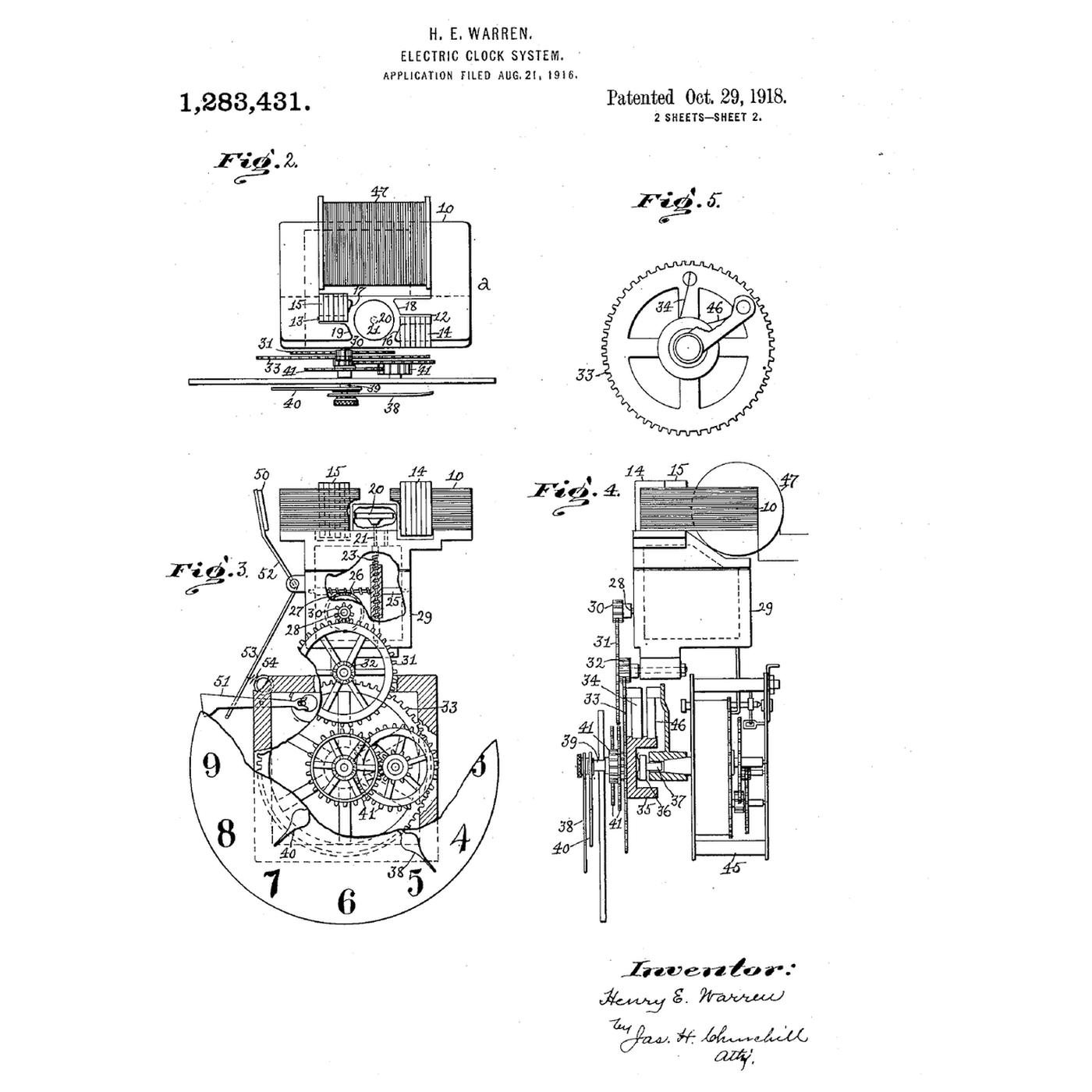
US 1,283,431, *Electric-Clock System*, filed 21 August 1916 and granted 29 October 1918, claims both halves: the self-starting synchronous motor, whose rotor is a plain hardened steel disc; and the system — a standard clock at the station, compared with a clock run from the supply, and the prime mover's speed adjusted to wipe out any excess or deficiency. Grids still correct their time error in the same way.
This rung simulates a wandering frequency with and without correction, and builds an Arduino clock that counts mains cycles through a low-voltage AC adapter.
Menengah
About 4 hours
Instruksi
1
1
Synchronous speed and time error
Synchronous speed and time error
Memuat notebook Jupyter…
2
2
Read Warren's motor and system
Read Warren's motor and system
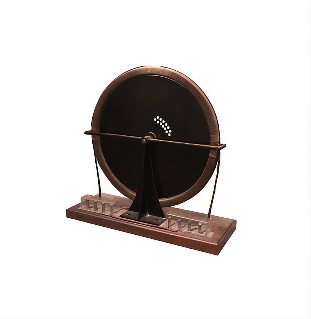
Figs. 2 to 5 of US 1,283,431 show the clock: a coil on a laminated field with two poles 12 and 13, each pole face split by **shading coils** 14 and 15 so the field sweeps round; in the space between the poles, the rotor 20 — "a disk of hardened steel and without windings or slots". It hangs a little below the middle of the pole faces so that, running, it rises and lifts the rotor and shaft off their bearings. A worm on a shaft of the train drives the hands; at 60 cycles the rotor turns 3600 times a minute.
A spring-driven auxiliary movement is held stopped by a lever while current flows, and released to run the clock if the current fails. Fig. 1 shows the system: an alternating-current generator, a standard clock at the station regulated daily by time signals, a comparison clock run from the supply, and the operator adjusting the prime mover until the two agree.
3
3
The sketch that counts the cycles
The sketch that counts the cycles
Counts one pulse per mains cycle through an opto-isolator and prints the grid's time every ten seconds.
grid_clock.inoarduino
Material untuk langkah ini:
 Arduino Uno R31 buah
 Adaptor keluaran AC tegangan rendah1 buah
 Opto-isolator Breakout1 buah
 Dioda1 buah
 Set Resistor1 buah
 Papan Rangkai1 buah
 Kabel Jumper1 buah
Alat yang dibutuhkan:
 Komputer dengan Arduino IDE
 Multimeter
4
4
Run it for a day against a network clock
Run it for a day against a network clock
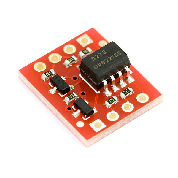
Check the adapter's label says **AC output** and measure it with the multimeter on AC volts before connecting anything. Wire the opto-isolator as the sketch's comment shows, set MAINS_HZ, and upload.
Start the Arduino exactly when a network-synced clock (a phone) reaches a whole minute, and note the time. Leave it running. Every few hours compare the sketch's elapsed time with the phone's: the difference is the grid's accumulated time error since you started. Over a day it moves by seconds and is pulled back — the correction Warren described.
Do not compare against the Arduino's own millis(): its ceramic resonator can drift much more than the grid does.
Alat yang dibutuhkan:
 Stopwatch
5
5
A synchronous clock showing the wrong time
A synchronous clock showing the wrong time
Synchronous clock faults.
Flow
Loading...
6
6
History and honest limits
History and honest limits
**Henry E. Warren** filed **US 1,283,431** on 21 August 1916, assigned to the Warren Clock Company of Ashland; it was granted 29 October 1918. His company's clocks were sold as Telechron, and for synchronous clocks to keep time the power stations had to control their frequency — which Warren's master clocks helped them do.
**Honest limits.** The simulation's frequency wander and correction rate are illustrative. A synchronous clock is only as good as the grid's time-error correction, which differs between grids and has at times been relaxed. Never work on mains voltage: the sketch is designed for a low-voltage AC adapter only.
Bahan
7- Placeholder
- Placeholder
- Opto-isolator Breakoutkomisi 10%1 buah$4.93
- 1 buahPlaceholder
- Placeholder
- Placeholder
- Placeholder
Alat yang Diperlukan
3- Placeholder
- Placeholder
- Placeholder
Estimasi total
Yang dibeli pembuatnya. Bahan tanpa harga didapat di tempat kamu membelinya.
Blueprint terkait
Blueprint ini berbagi pengetahuan — teknik, bahan, atau prinsip


CC0 Domain Publik
Cetak biru ini dirilis di bawah CC0. Anda bebas untuk menyalin, memodifikasi, mendistribusikan, dan menggunakan karya ini untuk tujuan apa pun, termasuk komersial, tanpa meminta izin.
Dukung Maker dengan membeli produk melalui Cetak Biru mereka di mana mereka mendapatkan Komisi Pembuat yang ditetapkan oleh Penjual, atau buat iterasi baru dari Cetak Biru ini dan masukkan sebagai koneksi di milik Anda sendiri.