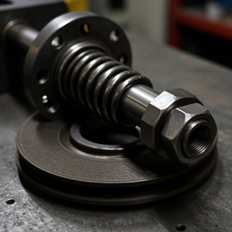


Torque Limiter
Instruksi
Build the friction stack
Build the friction stack
Two driving faces, one driven plate between them.
- Cut two 90 mm flanges and one 90 mm centre plate from 18 mm ply faced with 6 mm aluminium.
- Bore all three 8.0 mm.
- Key the two outer flanges to the shaft with M5 cup point set screws × 2.
- Leave the CENTRE plate free to rotate on the shaft, and fit the output sprocket or pulley to it.
- Face the centre plate with leather or cork on both sides.
Why a facing material. Metal on metal has a friction coefficient that changes with surface finish, temperature and the slightest trace of oil, so the slip torque wanders. Leather, cork or a woven lining is far more stable, and a stable coefficient is the whole point of a device whose job is to slip at a KNOWN torque.
Two friction faces rather than one doubles the torque for the same spring force, because both sides of the centre plate carry it. Multi-plate limiters simply extend that idea.Material untuk langkah ini:
 Kayu Lapis Birch Baltik1 lembar
 Batang Rata Aluminium1 buah
 Baut tanam ujung cekung2 buah
 Batang Bulat Aluminium1 buah
Alat yang dibutuhkan:
 Gergaji Ukir Listrik
 Bor Tanpa Kabel
 Set Mata Bor
 Set Kunci L (Hex)
 Set Kikir
 Jangka Sorong Digital 6 Inci
Add the spring and the adjusting nut
Add the spring and the adjusting nut
The spring sets the clamping force; the nut sets the spring.
- Fit a compression spring behind the outer flange, over the shaft.
- Thread the shaft end M10, or fit a captured M10 hex nut and washer to compress the spring.
- Add a locknut so the setting cannot drift.
- Mark a scale on the shaft or hub so spring compression can be measured and repeated.
Mark the scale before you calibrate. A torque limiter whose setting cannot be recorded and returned to is not a safety device — it is an adjustable mystery. Commercial limiters have a graduated collar for exactly this reason.
Use a spring whose working range you can actually measure. A very stiff spring reaches its limit in a fraction of a turn, making the setting almost impossible to control by hand.Material untuk langkah ini:
 Set Pegas Tekan1 set
 Ring Rata4 buah
 Mur Segi Enam2 buah
Alat yang dibutuhkan:
Set Kunci L (Hex)Jangka Sorong Digital 6 Inci Ragum MejaSet Kikir
Calibrate it — three settings, measured
Calibrate it — three settings, measured
An uncalibrated limiter protects nothing in particular.
- Clamp the shaft so it cannot turn.
- Wrap a cord round the output plate at a known radius and hang weights until it slips.
- Torque = weight × radius. Record it against the spring compression.
- Tighten the nut by a measured amount and repeat.
- Repeat once more, then plot torque against spring compression.
Alat yang dibutuhkan:
Jangka Sorong Digital 6 InciSet Kunci L (Hex)Ragum MejaTest the failure it is for — and the one it is not
Test the failure it is for — and the one it is not
Know both what it protects and what it does not.
- Set the limiter to a modest torque and drive the output against a gradually increasing load. It slips smoothly at the set point.
- Let it slip for thirty seconds, then stop and feel the friction faces.
- Now jam the output SUDDENLY at speed and observe.
- Compare what happened in the two cases.
Alat yang dibutuhkan:
Bor Tanpa Kabel StopwatchJangka Sorong Digital 6 Inci
Choosing the weak link, and history
Choosing the weak link, and history
Designing in a deliberate weak point is a mature engineering habit and it appears everywhere: the electrical fuse, the pressure relief valve, the shear pin, the crumple zone. In each case the designer decides in advance what will fail, so that the failure is cheap, safe and predictable rather than random and expensive.
Where friction limiters are standard: agricultural power take-off shafts, where a baler or mower can hit a stone; conveyor drives; machine tool feeds; and the packaging machinery whose jams would otherwise bend a screw conveyor. All are places where overloads are routine rather than exceptional, so a device that resets itself is worth far more than one that must be replaced.
Against the shear pin: the limiter slips and recovers with no parts consumed and no downtime, but its torque drifts as the linings wear or get contaminated. The shear pin fails at a precise, repeatable load determined by a known cross-section of a known material, but the machine stops dead until someone fits a new pin. Resettable and approximate against absolute and single-use — and which is right depends entirely on how often you expect the overload and how bad an unnoticed drift would be.
The dangerous failure mode to know about: a friction limiter that has been slipping repeatedly gets hot, glazes its linings and can end up transmitting LESS torque than intended — or, if contaminated and then dried, considerably more. Both are silent. Re-calibrating periodically is part of using one properly.
Bahan
7- 1 lembarPlaceholder
- 1 buahPlaceholder
- 2 buahPlaceholder
- 1 buahPlaceholder
- 1 setPlaceholder
- 4 buahPlaceholder
- 2 buahPlaceholder
Alat yang Diperlukan
8- 1 vendor sell this, none ship to you yetPlaceholder
- 1 vendor sell this, none ship to you yetPlaceholder
- Placeholder
- Placeholder
- Placeholder
- Placeholder
- Placeholder
- Placeholder
Blueprint terkait
Blueprint ini berbagi pengetahuan — teknik, bahan, atau prinsip
CC0 Domain Publik
Cetak biru ini dirilis di bawah CC0. Anda bebas untuk menyalin, memodifikasi, mendistribusikan, dan menggunakan karya ini untuk tujuan apa pun, termasuk komersial, tanpa meminta izin.
Dukung Maker dengan membeli produk melalui Cetak Biru mereka di mana mereka mendapatkan Komisi Pembuat yang ditetapkan oleh Penjual, atau buat iterasi baru dari Cetak Biru ini dan masukkan sebagai koneksi di milik Anda sendiri.