कला
सौंदर्य और कल्याण
हस्तशिल्प
संस्कृति और इतिहास
मनोरंजन
पर्यावरण
खाद्य और पेय
रिवर्स इंजीनियरिंग
विज्ञान
खेल
प्रौद्योगिकी
पहनने योग्य
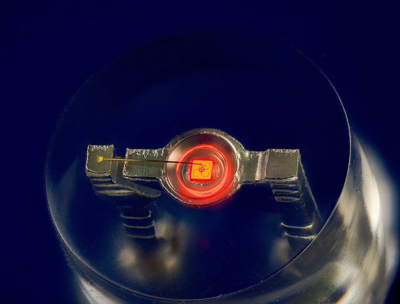

The Light-Emitting Diode
In 1907 Henry Joseph Round, working for Marconi, was probing carborundum crystals looking for a better radio detector. He put a potential across one and it glowed. He wrote a nine-line note to Electrical World describing a yellowish light at ten volts, added that other crystals gave green and orange and blue, and then went back to what he had actually been doing. Nobody followed it up for twenty years.
Oleg Losev did, in Nizhny Novgorod from 1927, and did it properly: he established that the light was not incandescence, measured the threshold, and published in Russian, German and English journals. He died in the siege of Leningrad in 1942 and his work was largely forgotten.
The device becomes real in 1962. In August, Biard and Pittman at Texas Instruments filed on a gallium arsenide diode emitting at 900 nm — infrared, invisible, and the first practical one. In October, Nick Holonyak at General Electric in Syracuse made gallium arsenide phosphide emit at 655 nm, and you could see it. He said at the time that these would eventually replace the incandescent lamp, which in 1962 was a remarkable thing to say and turned out to be an understatement.
What makes an LED worth a whole blueprint is a fact that no other light source shares. Its colour is not a filter, not a phosphor, not a temperature. It is a material property — the bandgap — converted directly into a photon energy, one photon per electron that crosses. Change the alloy, change the gap, change the colour, and nothing else about the device changes at all.
That also makes it the cheapest good experiment in physics. Because the energy an electron gives up is roughly the same energy the photon carries away, the voltage you have to apply is roughly the photon energy in volts — and if you measure that voltage for LEDs of several colours and plot it against one over the wavelength, the slope is Planck's constant over the electron charge.
It works. It also fails in an instructive way if you use a modern blue LED, and this blueprint tells you exactly why rather than quietly leaving blue out of the dataset.
मध्यवर्ती
6 hours
निर्देश
1
1
The colour is the bandgap, and nothing else
The colour is the bandgap, and nothing else
A diode under forward bias pushes electrons from the n side and holes from the p side into the same region. When one meets the other they recombine, and the electron drops from the conduction band to the valence band. It has to give up the energy difference somewhere.
IN SILICON it gives it up as heat, and this is not a small effect or a matter of purity. Silicon has an INDIRECT bandgap: the bottom of the conduction band and the top of the valence band sit at different crystal momenta, so an electron cannot simply drop across. It has to change momentum at the same time, which means a lattice vibration must participate, which means a three-body event, which is rare. So the electron waits, and long before its number comes up it has found some other way down. Silicon diodes do not glow and no amount of engineering makes them.
IN GALLIUM ARSENIDE the two band edges sit at the SAME momentum. It is a DIRECT gap. The electron drops straight across, emits a photon, and does it in nanoseconds. That single band-structure difference is why every LED is made from a compound semiconductor and none is made from silicon, and it is why the LED had to wait for III-V materials to be grown well.
THE PHOTON ENERGY IS THE GAP. E = hc over lambda, so:
gallium arsenide 1.42 eV 873 nm infrared
gallium arsenide phosphide, Holonyak's alloy, tunable through the red
gallium phosphide 2.26 eV 549 nm green, but indirect and therefore dim
indium gallium nitride, tunable 2.6 to 3.4 eV, blue through ultraviolet
TO GET A COLOUR YOU CHOOSE AN ALLOY. Gallium arsenide phosphide is GaAs with some of the arsenic replaced by phosphorus, and the gap slides continuously from 1.42 eV at zero phosphorus upward as you add more. Holonyak picked a composition that landed at 655 nm. Craford at Monsanto added nitrogen a decade later to reach yellow. Nothing else about the diode changes.
WHERE THE BLUE PROBLEM CAME FROM, and this is worth knowing because it is the reason for a Nobel Prize in 2014. Getting a wide gap is easy; gallium nitride has a gap of 3.4 eV and was grown in the 1970s. Getting a wide-gap material to be P-TYPE is the hard part, because the dopant levels sit too deep to ionise. Gallium nitride simply would not go p-type for twenty years. Isamu Akasaki and Hiroshi Amano cracked it in 1989 — the magnesium acceptors were being passivated by hydrogen, and an electron beam or a thermal anneal drove the hydrogen out. Shuji Nakamura at Nichia then made it manufacturable and bright. Blue arrived last, and once it did, white followed immediately: a blue die under a yellow phosphor.
SO WHITE LEDs ARE NOT LEDs of a white colour. They are a blue LED plus a phosphor, and that matters for the next step, because a white LED has the forward voltage of a BLUE one and emits nothing like a single wavelength. Do not put one in the dataset.
इस चरण के लिए सामग्री:
 एलईडी का वर्गीकृत सेट1 सेट
2
2
Measure the wavelength yourself, with a grating
Measure the wavelength yourself, with a grating
You could take the wavelength off the datasheet. Do not. Half the point of this experiment is that both quantities are measured, and a transmission grating measures wavelength to a couple of percent with a ruler.
WHAT YOU NEED. A transmission grating sheet — 1000 lines per millimetre is the common one, so the line spacing d is 1.000 micrometre. A metre rule. A dark room. And a way to make a narrow source: run the LED behind a slit cut in card, 0.5 mm wide, or simply use the LED die itself at a distance, which is small enough.
THE GEOMETRY. Mount the grating vertically. Put the LED behind it at distance L, on the axis, so you look through the grating at the LED. You will see the LED straight ahead — that is the zero order — and a copy of it to each side, which is the first order. Measure the distance x from the centre to the first-order copy, along a rule held across the field at the LED's distance.
Then sin(theta) = x over the square root of (x squared plus L squared), and the grating equation for first order is simply lambda = d sin(theta).
MEASURE IT PROPERLY. Take x on BOTH sides and average them; that cancels any misalignment of the grating, and it is the single biggest source of error. Get L with a tape, not by estimating. Keep L large — half a metre or more — because the angle error falls as L grows.
WHAT YOU SHOULD GET, roughly, so you know when something is wrong:
red 620 to 640 nm
amber 600 to 610 nm
yellow 585 to 595 nm
green 560 to 570 nm for the traditional gallium phosphide sort
blue 465 to 475 nm
AND HERE IS THE TRAP, stated plainly because it will otherwise wreck your result.
GREEN LEDs COME IN TWO COMPLETELY DIFFERENT KINDS. The traditional green is gallium phosphide, emits near 565 nm, and has a forward voltage around 2.2 V. The modern bright green — the one in traffic lights and in most LED assortments sold today — is indium gallium nitride, the SAME material family as blue, emits near 525 nm, and has a forward voltage around 3.2 V. It is a blue-technology device tuned green.
If you put a modern InGaN green in this dataset it will sit far off the line and you will conclude your measurement is broken. It is not. You are measuring two different device families and pretending they are one.
HOW TO TELL THEM APART without a datasheet: measure the forward voltage first. Below about 2.4 V it is a traditional gallium-phosphide or gallium-arsenide-phosphide part. Above about 2.7 V it is a nitride part. Sort them into two groups before you plot anything.
DO NOT USE A WHITE LED at all, for the reason in step 1. Do not use an infrared LED unless you have a phone camera to see it with; most phone cameras will, and it is a good addition to the dataset because it sits at the far end of the line.
इस चरण के लिए सामग्री:
एलईडी का वर्गीकृत सेट1 सेट विवर्तन जालिका शीट (1000 रेखा/मिमी)1 शीट
आवश्यक उपकरण:
 रूलर
रूलर प्रयोगशाला श्रेणी का डिजिटल मल्टीमीटर
3
3
Drive it two ways, and see why one of them drifts
Drive it two ways, and see why one of them drifts
You need a defined current to measure a forward voltage that means anything, so build the drive properly before taking the data.
THE RESISTOR VERSION on the left is what everyone builds. The current is the supply voltage minus the LED's forward voltage, divided by the resistor. It works, and it has two weaknesses that this experiment makes visible.
It depends on Vf, which is the thing you are trying to measure — so a red LED and a blue LED on the same resistor run at completely different currents, and since Vf itself depends on current, you are comparing them at different points on their curves.
And Vf has a temperature coefficient of roughly minus two millivolts per kelvin, the same as any diode. Warm the LED with your fingers and Vf falls, so the resistor drops more, so the current rises, so it warms further. On a 5 V supply with a 150 ohm resistor this is a mild effect. On a 3.3 V supply driving a blue LED, where the resistor only drops 0.3 V, it is not mild at all — a 20 degree rise changes the current by more than ten percent.
THE CURRENT SOURCE on the right removes both problems. The transistor's base sits at a fixed reference, its emitter one Vbe below that, and the emitter resistor therefore sees a fixed voltage and passes a fixed current — which is the LED's current. Vf does not appear anywhere in that expression. Swap a red LED for a blue one and the current does not change.
For this experiment, build the current source. Set it to a low current — 0.1 to 1 mA — and use the SAME current for every LED. That is what makes the comparison across colours legitimate.
WHY A LOW CURRENT. The measured forward voltage is the junction voltage plus the current times the series resistance of the bulk material and the contacts. That series term is pure error for our purposes, and it is proportional to current. At 20 mA it can be a couple of tenths of a volt; at 0.1 mA it is negligible. Measuring at low current gets you much closer to the true junction voltage, and therefore much closer to the bandgap.
ONE RULE THAT LOOKS ARBITRARY AND IS NOT. Never parallel LEDs across a single resistor. Forward voltages vary between parts, the one with the lowest takes the largest share of the current, that one heats, its Vf drops further, and it takes more still. It is a positive feedback loop and it ends with one very bright LED and several dark ones, or one dead one. Series strings are fine, because the same current flows through every element by definition.
KiCanvas व्यूअर लोड हो रहा है...
पेशेवर PCB डिज़ाइन व्यूअर
इस चरण के लिए सामग्री:
एलईडी का वर्गीकृत सेट1 सेट प्रतिरोधक किट1 किट
 ट्रांजिस्टरों का वर्गीकृत सेट1 सेट
आवश्यक उपकरण:
 Breadboard
 बेंच विद्युत-आपूर्तिप्रयोगशाला श्रेणी का डिजिटल मल्टीमीटर
4
4
Planck's constant, and the honest error budget
Planck's constant, and the honest error budget
Jupyter नोटबुक लोड हो रही है…
आवश्यक उपकरण:
 डेस्कटॉप कंप्यूटर
सामग्री
4- प्लेसहोल्डर
- प्लेसहोल्डर
- प्लेसहोल्डर
- प्लेसहोल्डर
आवश्यक उपकरण
5- प्लेसहोल्डर
- प्लेसहोल्डर
- Breadboard - Classic10% कमीशन₹906.43
- प्लेसहोल्डर
- प्लेसहोल्डर
संबंधित ब्लूप्रिंट
ये ब्लूप्रिंट ज्ञान साझा करते हैं — तकनीक, सामग्री या सिद्धांत


CC0 पब्लिक डोमेन
यह ब्लूप्रिंट CC0 के तहत जारी किया गया है। आप बिना अनुमति माँगे इस कार्य को किसी भी उद्देश्य के लिए कॉपी, संशोधित, वितरित और उपयोग करने के लिए स्वतंत्र हैं।
उनके ब्लूप्रिंट के माध्यम से उत्पाद खरीदकर मेकर का समर्थन करें जहाँ वे मेकर कमीशन कमाते हैं जो विक्रेताओं द्वारा निर्धारित होता है, या इस ब्लूप्रिंट का नया संस्करण बनाएँ और राजस्व साझा करने के लिए इसे अपने ब्लूप्रिंट में कनेक्शन के रूप में शामिल करें।