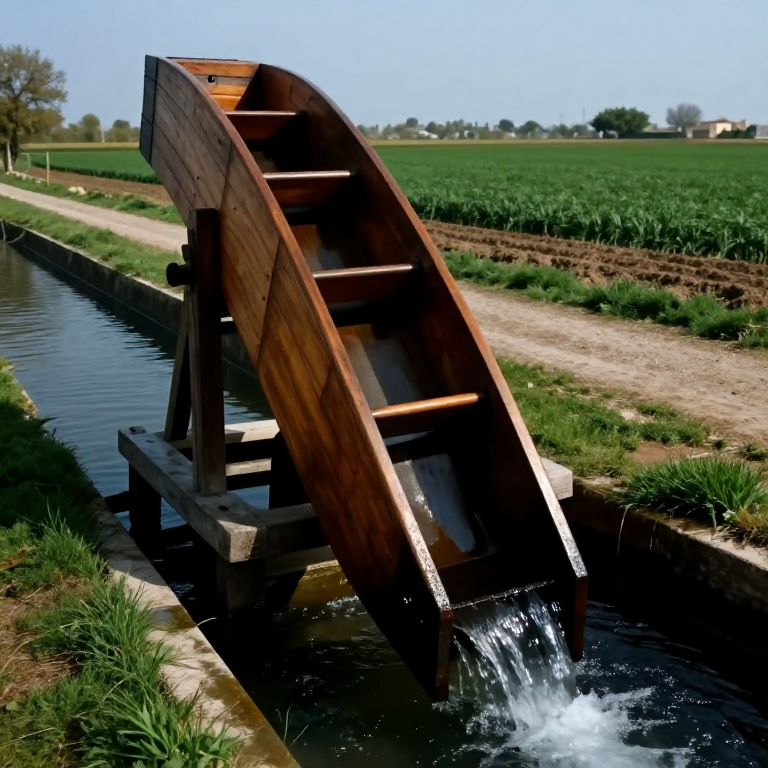
Building an Archimedes' Screw — The Spiral Pump That Lifts Water Uphill
The Archimedes' screw is a helical device that lifts water from a lower level to a higher level by rotating a screw-shaped surface inside a close-fitting cylindrical tube. Water enters at the lower open end, becomes trapped in the helical cavity between the screw and the cylinder wall, and is carried upward as the screw turns — climbing the spiral staircase of the helix one pocket at a time. The device is named for Archimedes of Syracuse (~287–212 BCE), though ancient evidence suggests it may have been used in Babylon earlier, and some scholars attribute its practical development to Egyptian engineers working on Nile irrigation.
The principle was described by Vitruvius in 'De Architectura' (~25 BCE): the screw must be set at an angle to the horizontal — ideally 30–37° — which is a direct consequence of the helix geometry. At the optimal angle, each pocket of water remains stable as it travels upward; at shallower angles the pockets slosh backward; at steeper angles the mechanical advantage decreases and more power is needed to turn the screw. The exact optimal angle of 30° was understood geometrically by ancient engineers as the angle that maximises flow per unit of torque.
Greek and Roman mines used Archimedes' screws to dewater excavations — the same application as modern bilge pumps. Ancient Egyptian agriculture used them to lift Nile floodwater into irrigation channels. The Romans used them in the silver mines of Rio Tinto in Spain, where a cascade of eight screws (four on each side) lifted water 30 metres from flooded lower galleries to drainage tunnels above. Today, the same principle drives modern Archimedean screw turbines for hydroelectric generation — the device running in reverse, with water pushing the screw to generate electricity. It remains one of the simplest, most reliable pumping mechanisms ever devised, with no valves or seals to fail.
دستورالعملها
Calculate dimensions and set the 30–37° installation angle
Calculate dimensions and set the 30–37° installation angle
The Archimedes' screw must be built to specific proportions to function correctly. The classical design described by Vitruvius uses the following ratios: the screw's outer diameter D, the pitch of the helix P (the axial distance between one complete turn and the next), and the installation angle θ are related by the condition that water pockets remain stable during rotation. Vitruvius specified that the pitch P should equal the outer circumference divided by eight — approximately P = (π × D) / 8, giving a ratio of roughly 0.39D per turn. For a working screw 20 cm in outer diameter and 1.5 m long, the pitch ≈ 7.9 cm, producing approximately 19 helical turns along the length.
The installation angle of 30–37° is not arbitrary: at exactly 30° the incline angle matches the arctangent of the helix pitch-to-circumference ratio for this classical geometry, meaning each water pocket sits level as the screw turns. Mark the installation angle on the site using a plumb bob and a protractor batten. Prepare two supports (frames of timber or masonry) that hold the screw at this angle with the lower end submerged in the water source and the upper end discharging into the irrigation channel or tank.
ابزارهای مورد نیاز:
 Shovel
Select and prepare the central shaft
Select and prepare the central shaft
The central shaft of the screw must be straight, strong, and impervious to water-induced rot. Select a dense hardwood log — oak or elm — approximately 8–10 cm in diameter and 10% longer than the intended screw length (the extra length forms the journal ends that rest in the bearing supports). The shaft must be as straight as a carpenter's eye can judge — sight along its length from both ends and rotate it on a flat surface, watching for run-out. A visibly curved shaft causes vibration and bearing wear from the moment of installation.
Debark the log and let it air-dry for at least two weeks if freshly cut. Then plane or drawknife the surface to a consistently round cross-section. Mark the shaft axis clearly with a chalk line run from end to end — this line is the reference for laying out the helix position of the helical blade. Coat the shaft with pine tar (hot-applied) to protect against water absorption and rot.
مواد مورد نیاز این مرحله:
 Hardwood Block3 piece
ابزارهای مورد نیاز:
 Hand Saw
 Sharp Knife
Lay out the helix pattern on the shaft
Lay out the helix pattern on the shaft
To place the helical blade at a consistent pitch, you need a geometric method for marking the spiral path on the shaft. Cut a right-triangle paper or thin wood template with the short leg equal to the shaft circumference (π × 8 cm ≈ 25.1 cm for an 8 cm shaft) and the long leg equal to the desired pitch (7.9 cm for the Vitruvian proportion at 20 cm outer diameter). Wrapping this triangle around the shaft with the hypotenuse forming a helix traces out the correct spiral path — this is exactly how a barber's pole stripe is drawn and is the mathematical definition of the helix.
Mark the helix path on the shaft using a sharp pencil or marking knife. This line is where the edge of the helical blade will attach. Make multiple complete turns along the shaft's working length. Check that the spacing between adjacent marked turns is consistent — any variation indicates the template slipped during marking and must be corrected before cutting begins.
Carve the helical blade from wooden strips
Carve the helical blade from wooden strips
The helical blade (the 'flight') is the screw surface that traps water in its pockets and carries it upward. For a wooden screw, the blade is built up from thin strips of green (freshly cut, still flexible) oak or willow, approximately 1 cm thick and 6 cm wide — the 6 cm width represents the flight's radial extension from the shaft surface to the outer diameter. Green wood bends without breaking; dry wood splits when twisted to a helical curve.
Soak the strips in boiling water for 30 minutes to soften the lignin further before bending. Clamp one end of the first strip to the shaft at the first helix mark, then slowly wind the strip along the marked helix path, clamping each section as you go. Allow the shaped strip to dry completely in position (1–2 days minimum) before removing clamps — once dry, the wood holds its helical shape permanently. Overlap and peg adjacent strips to build the flight to a consistent 6 cm radial height all the way along the shaft.
مواد مورد نیاز این مرحله:
Hardwood Block2 piece Iron Nails40 piece
Build the outer wooden cylinder
Build the outer wooden cylinder
The outer cylinder must fit closely around the helical blade — the clearance between blade tip and cylinder inner wall should be 2–3 mm maximum. Larger clearance allows water to slip back past the blade, reducing flow rate and efficiency. The cylinder is built from tapered stave boards (like a barrel), curved and coopered together around a temporary form set to the outer screw diameter (20 cm in our design). Use 2 cm thick oak staves approximately 6 cm wide, angled at their edges to fit tightly together in a circle.
Drive iron hoops over the staved cylinder to pull the staves tight — use at least four hoops along a 1.5 m cylinder, positioned at quarter-points of the length. Drive the hoops with a wooden mallet and iron hoop driver from the top down. Caulk the stave seams from inside with oakum (hemp fibre) dipped in pine pitch, then drive the caulk tight with a caulking iron. The cylinder must be watertight — any significant leak path between staves allows the pressurised water pockets to short-circuit the helix and flow backward.
مواد مورد نیاز این مرحله:
Hardwood Block4 pieceIron Nails30 pieceابزارهای مورد نیاز:
 Hammer (2 kg)
Fit the screw assembly inside the cylinder
Fit the screw assembly inside the cylinder
Slide the helical screw carefully inside the cylinder. The outer edges of the helical blade should just clear the cylinder inner wall — you should hear a slight rasping as the screw turns inside the cylinder if clearance is correct. If the blade binds (will not turn), the cylinder is too tight — wet the assembly to swell the wood slightly, then mark the high spots with marking chalk and pare them down with a chisel. If the blade spins freely with visible daylight between blade and cylinder wall, the clearance is too large and water will bypass the flight rather than being carried upward.
Mark the cylinder to correspond with the shaft's top and bottom journal ends. The cylinder must be keyed or pinned to prevent it rotating with the shaft — only the internal screw rotates; the cylinder is stationary. Bore two bearing holes through the cylinder ends at the shaft centreline and fit hardwood or bronze bushing inserts that allow the shaft to rotate freely while supporting its weight.
Install the screw at 30–37° on its support frames
Install the screw at 30–37° on its support frames
Mount the completed screw on the pre-built support frames at the calculated 30–37° angle. The lower end of the shaft journal rests in a bearing block set into the lower frame — this bearing must be submerged in the water source during operation, so use a dense, water-resistant wood (elm heartwood is traditional) or bronze for the lower bearing. The upper shaft journal rests in a bearing at the top of the upper frame, where the handle or drive wheel attaches.
The lower end of the cylinder must be open and submerged approximately 5 cm below the water surface. The upper end must be open and positioned over the receiving channel or tank. Ensure the cylinder is firmly lashed or spiked to the support frames — vibration during operation loosens a cylinder that is merely resting on the frames, and a shifting cylinder can cause the rotating screw to bind catastrophically mid-operation.
Seal the blade-to-cylinder contact surface with pine pitch
Seal the blade-to-cylinder contact surface with pine pitch
Heat pine pitch (resin) in a small iron pot until fluid (approximately 100–150°C). Using a brush made from bound plant fibres, paint the contact surface between the helical blade edges and the cylinder inner wall with a thin film of pitch. Work with the screw positioned horizontally so the pitch does not drip and pool. Allow the pitch to cool and harden (10–15 minutes at ambient temperature) before testing rotation.
The pitch seal compensates for the small clearance between blade and cylinder, essentially creating a sliding seal that moves with the blade during rotation. After the first few hours of operation, the pitch will be polished smooth by the rotating blade, reducing friction. Re-pitch the seal annually or whenever water output drops significantly — the pitch gradually wears away in a working screw, particularly in abrasive or sediment-laden water.
Attach the handle or drive arrangement
Attach the handle or drive arrangement
The upper end of the shaft extends 30–40 cm above the upper bearing and is fitted with a handle for hand-cranking, or a pole arrangement for animal drive (oxen or donkeys walking in a circle), or a wooden crown wheel for connection to a water wheel or windmill for automatic operation. For hand operation, fit a T-shaped handle: a horizontal wooden bar 60 cm long mortised through the top of the shaft at right angles, so two workers can stand side-by-side and turn the screw by walking around it.
For a 20 cm diameter screw lifting water 1.5 m at 30°, turning the screw at 60 rpm (approximately one turn per second — a comfortable manual pace) delivers roughly 10–15 litres per minute. At this flow rate, two workers can irrigate approximately 0.1 hectares of crops per hour, or dewater a shallow excavation of 5 × 5 × 0.2 m in about 30 minutes. Increasing the screw diameter to 40 cm quadruples the flow to 40–60 litres per minute for the same rotational speed.
مواد مورد نیاز این مرحله:
Hardwood Block1 pieceWaterproof the complete assembly with pine tar
Waterproof the complete assembly with pine tar
Hot-apply pine tar to all exterior wooden surfaces of the cylinder and the exposed ends of the shaft. Pine tar (produced by the destructive distillation of pine wood at 250–300°C) penetrates wood fibres, repelling water and preventing fungal decay. Apply it hot using a cloth-wrapped paddle, working it into all joints and end-grain surfaces where moisture enters most readily. End grain absorbs water at 10–15 times the rate of face grain — focus extra tar on the cylinder stave ends and shaft journal ends.
Allow the tar to cure for 24 hours before the first wet run. The surface will remain tacky for several days and gradually harden over weeks of service. Pine tar treatment was the standard method for preserving waterlogged wooden mill components throughout antiquity and the medieval period — the same method used for ship timbers and Viking longships.
Commission with a first-run flow test
Commission with a first-run flow test
Lower the screw into position with the bottom end submerged 5 cm below the water surface. Begin turning slowly — 20–30 rpm for the first few minutes to allow the pitch seals to bed in and the bearings to warm up. Water should appear at the upper end within two full rotations. If no water appears after five rotations, the installation angle is likely too steep (water cannot be trapped in pockets) or the cylinder seams are leaking severely (water escapes faster than it is pumped).
Gradually increase rotational speed to the target 60 rpm. Collect the output in a calibrated container for one minute to verify the flow rate matches calculated expectations. A measured flow significantly below expectation (less than 60% of calculated) indicates excessive blade-to-cylinder clearance; greater-than-expected flow indicates a shallower installation angle than measured (more water per pocket due to larger pocket volume). Document the actual flow rate for this installation for use in irrigation scheduling calculations.
Reverse operation as a turbine (advanced)
Reverse operation as a turbine (advanced)
The Archimedes' screw is reversible: if water is poured in at the top end and allowed to fall through the helical cavity by gravity, the weight of the descending water rotates the screw, and this rotation can be harnessed to drive other machinery. This is the Archimedes Screw Turbine — modern installations generate 50 kW to 1 MW of electrical power from low-head water drops of 1–10 metres, exactly the range where conventional turbines are inefficient. The same geometry that makes the screw an efficient pump makes it an efficient turbine.
To test the reversible operation with your hand-built screw, dam a small water source to create a 1–2 metre head difference, mount the screw at 30° with the upper end in the high reservoir and the lower end discharging into the tailrace, and allow gravity to drive water down through the helix. The shaft should rotate measurably against a light braking load — the torque available from a 20 cm, 1.5 m screw at 1 m head is approximately 0.5–1 Nm, enough to feel clearly in the hand.
Maintenance and bearing replacement schedule
Maintenance and bearing replacement schedule
The most wear-prone components in a wooden Archimedes' screw are the lower shaft bearing (permanently submerged) and the pitch seal between blade and cylinder. Inspect the lower bearing monthly — it should show wear as a slight oval deformation of the originally round bearing bore. Replace the bearing insert when the oval wear reaches 10% of the bore diameter (approximately 8 mm oval vs 8 mm round). Replace the bearing with elm heartwood (the densest, most water-resistant domestic timber) or, for longer service, carve a replacement from lignum vitae if available.
Re-pitch the blade seal annually, or whenever the delivered flow rate drops more than 20% from the commissioning measurement. Remove the screw from the cylinder, clean the blade edges and cylinder inner wall with a stiff brush, and apply fresh pitch. Inspect the stave joints of the cylinder for open seams — re-caulk any that admit light. A correctly maintained wooden Archimedes' screw can serve for 10–20 years before requiring full reconstruction.
مواد نقشههای متصل
نقشههای مرتبط
این نقشهها دانش مشترکی دارند — تکنیکها، مواد یا اصول
Related blueprints
Other builds that share materials, tools, or techniques with this one.

CC0 مالکیت عمومی
این نقشه تحت مجوز CC0 منتشر شده است. شما آزاد هستید آن را کپی، ویرایش، توزیع و برای هر هدفی بدون نیاز به اجازه استفاده کنید.
با خرید محصولات از طریق نقشه از سازنده حمایت کنید و او کمیسیون سازنده تعیین شده توسط فروشندگان، دریافت میکند یا یک نسخه جدید از این نقشه ایجاد کنید و آن را به عنوان اتصال در نقشه خود قرار دهید تا درآمد به اشتراک گذاشته شود.