Building a Roman Groma — The Surveying Instrument That Laid Out an Empire
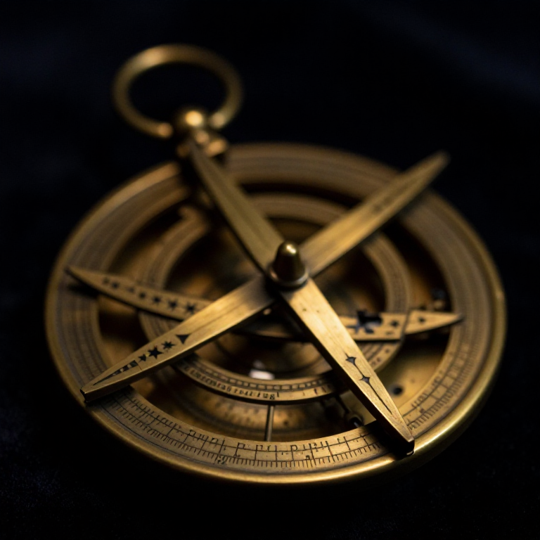
The groma is the defining tool of Roman land surveying and engineering. Without it, the straight roads, precisely planned cities, perfectly rectangular field grids (centuriation), and accurately aligned military camps that characterise Roman civilisation would have been impossible. The groma enabled the agrimensores (land surveyors) to establish straight lines and right angles over distances of kilometres with an accuracy that modern surveyors using the same instrument can replicate to within a fraction of a degree.
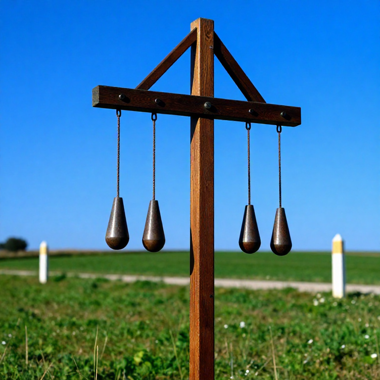
The instrument consists of a vertical staff (ferramentum) planted in the ground, with a horizontal rotating arm (rostrum) mounted on a swivel bracket offset to one side of the staff. From each end of two cross-arms arranged at right angles, a plumb bob (perpendiculum) hangs on a cord. By sighting along two opposing plumb bobs, the surveyor can establish a perfectly straight line. By sighting along an adjacent pair, they can set a line at exactly 90 degrees — a right angle. The offset mounting of the rotating arm means the surveyor can sight directly over the ground station point without the staff obscuring the view.
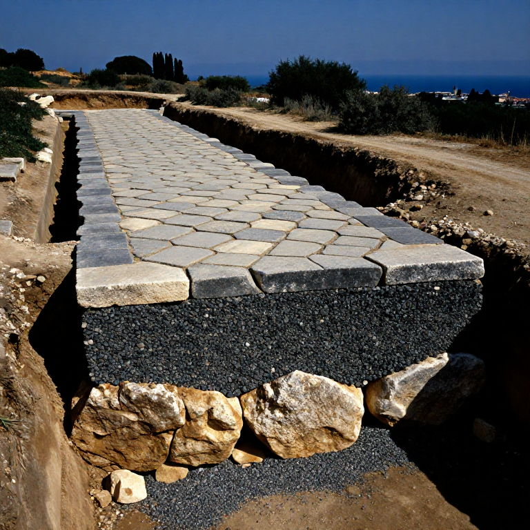
The groma was so central to Roman surveying practice that its image appears on the tomb of the surveyor Lucius Aebutius Faustus at Pompeii, along with the inscription that he was an agrimensor. Roman colonies and military camps were laid out using the groma to establish the two primary axes — the cardo maximus (north-south) and the decumanus maximus (east-west) — from which a grid of streets was projected across the entire settlement. This grid planning survives in hundreds of European cities today: Turin, Florence, York, and Cologne all retain street grids that originated with a Roman groma.
دستورالعملها
Select and prepare the vertical staff timber
Select and prepare the vertical staff timber
Cut a straight-grained hardwood staff approximately 1.5–1.8 metres long and 3–4 cm in diameter. Ash or oak are ideal — both are strong, straight-grained, and resistant to warping. The staff must be perfectly straight: roll it on a flat surface and reject any that rock. Season the wood if newly cut (green wood warps as it dries, destroying the instrument's accuracy). Taper the lower end to a blunt point for driving into the ground. Sand the entire shaft smooth. Alternatively, a piece of straight iron rod or bronze rod of similar diameter produces a more durable and precise staff — the Romans used iron ferramentum (hence the name) on quality instruments.
مواد مورد نیاز این مرحله:
 Hardwood Shaft (2m)1 piece
ابزارهای مورد نیاز:
 Hand Saw
 Sharp Knife
Carve the swivel bracket (gnomon bracket)
Carve the swivel bracket (gnomon bracket)
The bracket is the most critical component — it connects the horizontal cross-arm assembly to the vertical staff via a rotating joint, and it must be offset (cantilevered out) so that sighting lines pass directly over the staff's ground point without obstruction. Carve the bracket from a single dense hardwood block (approximately 15 × 8 × 5 cm) or forge it from iron. One end receives the vertical staff through a snug but rotating hole drilled 3 cm from the end. The other end is a horizontal socket that receives the rotating cross-arm pivot pin. The offset of the bracket (distance from staff centre to rotating arm centre) should be 8–12 cm. The bracket must rotate freely around the staff when loosened but lock firmly when tightened against the staff with a wedge or iron collar.
مواد مورد نیاز این مرحله:
 Hardwood Block1 piece
ابزارهای مورد نیاز:
 Awl
AwlCut the two cross-arms to equal lengths
Cut the two cross-arms to equal lengths
The horizontal cross consists of two arms of equal length (approximately 40–50 cm each) arranged at exactly 90 degrees to each other, mounted at the centre of the assembly on the rotating pivot. Cut both arms from the same piece of straight-grained hardwood to ensure identical density and minimal warping. Sand both to equal dimensions: approximately 2 cm × 2 cm square section. Drill a centring hole through both arms at the midpoint for the pivot pin — the intersection of the two arms. The two arms must be joined at exactly 90 degrees: test with a carpenter's square and trim as needed until both the assembled angle and the arm lengths are precise.
مواد مورد نیاز این مرحله:
Hardwood Block1 pieceVerify the 90-degree angle using the 3-4-5 triangle method
Verify the 90-degree angle using the 3-4-5 triangle method
Before assembling the cross-arms permanently, verify the right angle using the Pythagorean 3-4-5 method: measure 3 units along one arm from the centre and 4 units along the other arm from the centre. If the angle is exactly 90 degrees, the diagonal between those two points will measure exactly 5 units (by Pythagoras: 3² + 4² = 5²). For example, use 30 cm + 40 cm — the diagonal should be exactly 50 cm. If the diagonal is short, the angle is acute; if long, obtuse. Trim one arm's junction surface slightly and recheck until the 3-4-5 test passes to within 1 mm. Roman agrimensores knew this theorem and used it routinely for orthogonal layout.
مواد مورد نیاز این مرحله:
 Hemp Cord2 meter
Drill holes at each cross-arm tip for plumb bob cords
Drill holes at each cross-arm tip for plumb bob cords
Drill or bore a small hole (4–6 mm diameter) through the centre of each arm tip — four holes total, one at each end of each arm. These holes receive the plumb bob suspension cords. The holes must be precisely at the geometric tip of each arm, not offset to one side — any asymmetry in cord position introduces a systematic sighting error. Smooth the inside of each hole with a rounded awl tip so that the cord hangs freely without friction. Thread a short loop of fine cord through each hole and knot it above the hole to create the suspension point for the plumb bob.
ابزارهای مورد نیاز:
AwlCast or carve four plumb bobs
Cast or carve four plumb bobs
Make four identical plumb bobs from lead or dense stone (e.g. magnetite, haematite, or dense limestone). Each bob should weigh 50–100 g and have a pointed bottom tip and a hole or hook at the top for the cord. Lead is the best material — it is very dense (11,340 kg/m³), cast easily, and rust-free. Melt lead scraps in a clay crucible over charcoal and pour into a cone-shaped mould scratched into damp sand. The four bobs must be as close to equal weight as possible (within 5 g of each other) — unequal weight causes the lighter bobs to swing more in light wind, degrading accuracy. File off any casting flash and check the point is centred by hanging each bob and observing it spin.
Cut and attach the plumb bob cords to equal length
Cut and attach the plumb bob cords to equal length
Cut four cords of identical length (approximately 30–40 cm) from fine twisted linen thread or thin leather thong. Tie each cord to a plumb bob hook with a secure reef knot, then thread the free end through the corresponding tip hole and knot it above with a stop knot. The bottom of each hanging plumb bob should be at the same height — hold the assembled cross horizontal and check that all four points are at equal distance below the arm plane. Trim any long cord by re-knotting. In use, the plumb bobs are most accurate in calm conditions; even a light breeze sets them swinging. Roman surveyors worked at dawn for this reason, when wind is typically minimal.
مواد مورد نیاز این مرحله:
Hemp Cord2 meterAssemble the cross-arms onto the bracket pivot
Assemble the cross-arms onto the bracket pivot
Drive a smooth iron or hardwood pivot pin through the centring hole in the cross-arm assembly and into the socket of the bracket. The cross must rotate freely on this pivot so that the surveyor can spin it to any direction. The pivot pin should be a close fit — enough clearance to rotate without binding, but tight enough that the cross does not wobble. Secure the pin with a small iron collar or a wedge beneath the cross that takes the vertical load, preventing the arm from dropping off the pivot. The cross should spin smoothly through 360 degrees and stop without oscillation when released.
مواد مورد نیاز این مرحله:
 Iron Nails4 piece
Mount the bracket on the staff and test the rotation
Mount the bracket on the staff and test the rotation
Slide the bracket onto the top of the vertical staff, with the rotating cross-arm assembly cantilevered to one side. Tighten the bracket against the staff with a wooden wedge driven through a slot in the bracket collar, or with an iron ring collar that clamps when tightened with a peg. The bracket should be absolutely rigid when locked but rotate freely around the staff when the clamp is loosened — this allows the surveyor to re-orient the cross arms without re-seating the staff. Mount the bracket approximately 1.3–1.5 metres up the staff so that the plumb bobs hang at approximately eye level when the instrument is planted in the ground.
Plant the staff and align the first sight line
Plant the staff and align the first sight line
Drive the staff into the ground at the survey station point until it is fully vertical — check verticality in two directions using a separate plumb bob held beside the staff. Allow the plumb bobs on the cross-arms to come to rest in still air (wait 30–60 seconds after any movement). To sight a line, stand behind the instrument and align the near plumb bob cord with the far plumb bob cord along the desired direction — sight across the two cords as you would sight a rifle. When both cords appear superimposed, the line from you through the instrument to the target is perfectly straight. Have an assistant stand at the target distance and guide them with hand signals to the exact alignment.
Establish a right-angle line using the perpendicular cross-arm
Establish a right-angle line using the perpendicular cross-arm
After sighting the first line, sight along the perpendicular pair of plumb bobs (at 90 degrees to the first alignment) to establish a line at a right angle. In Roman city planning, the cardo maximus (main north-south street) was first aligned using the groma along the cardinal north direction (established using a shadow stick or the stars). Then the decumanus maximus was established at 90 degrees using the groma's perpendicular cross-arm. From the intersection of these two axes, parallel lines were projected at regular intervals (the insulae block spacing, typically 75–100 m in Roman colonies) using the groma set up at each new point along the baseline. This creates the regular street grid (centuriation) visible from satellite imagery over much of southern Europe today.
Calibrate accuracy over a long baseline
Calibrate accuracy over a long baseline
Test the completed groma over a long baseline of 200+ metres. Establish a straight line from point A to point B using the groma at A. Then set up the groma at B and sight back to A — the sightline should pass exactly through A. Any systematic error (a plumb bob hole offset, a warped cross-arm, or a non-perpendicular cross junction) will show up as a deviation. Roman surveyors achieved angular accuracies of 0.1–0.3 degrees using well-made gromas in calm conditions. For road alignment over 100 km, this translates to a lateral error of 170–520 metres — large by modern GPS standards but remarkable for naked-eye sighting. Adjust any arm-length discrepancy by carving a small amount from the longer arm until opposite plumb lines are truly parallel when hanging.
مواد
4- 1 pieceجایگزین
- 2 pieceجایگزین
- 4 pieceجایگزین
مواد نقشههای متصل
نقشههای مرتبط
این نقشهها دانش مشترکی دارند — تکنیکها، مواد یا اصول
Related blueprints
Other builds that share materials, tools, or techniques with this one.


CC0 مالکیت عمومی
این نقشه تحت مجوز CC0 منتشر شده است. شما آزاد هستید آن را کپی، ویرایش، توزیع و برای هر هدفی بدون نیاز به اجازه استفاده کنید.
با خرید محصولات از طریق نقشه از سازنده حمایت کنید و او کمیسیون سازنده تعیین شده توسط فروشندگان، دریافت میکند یا یک نسخه جدید از این نقشه ایجاد کنید و آن را به عنوان اتصال در نقشه خود قرار دهید تا درآمد به اشتراک گذاشته شود.