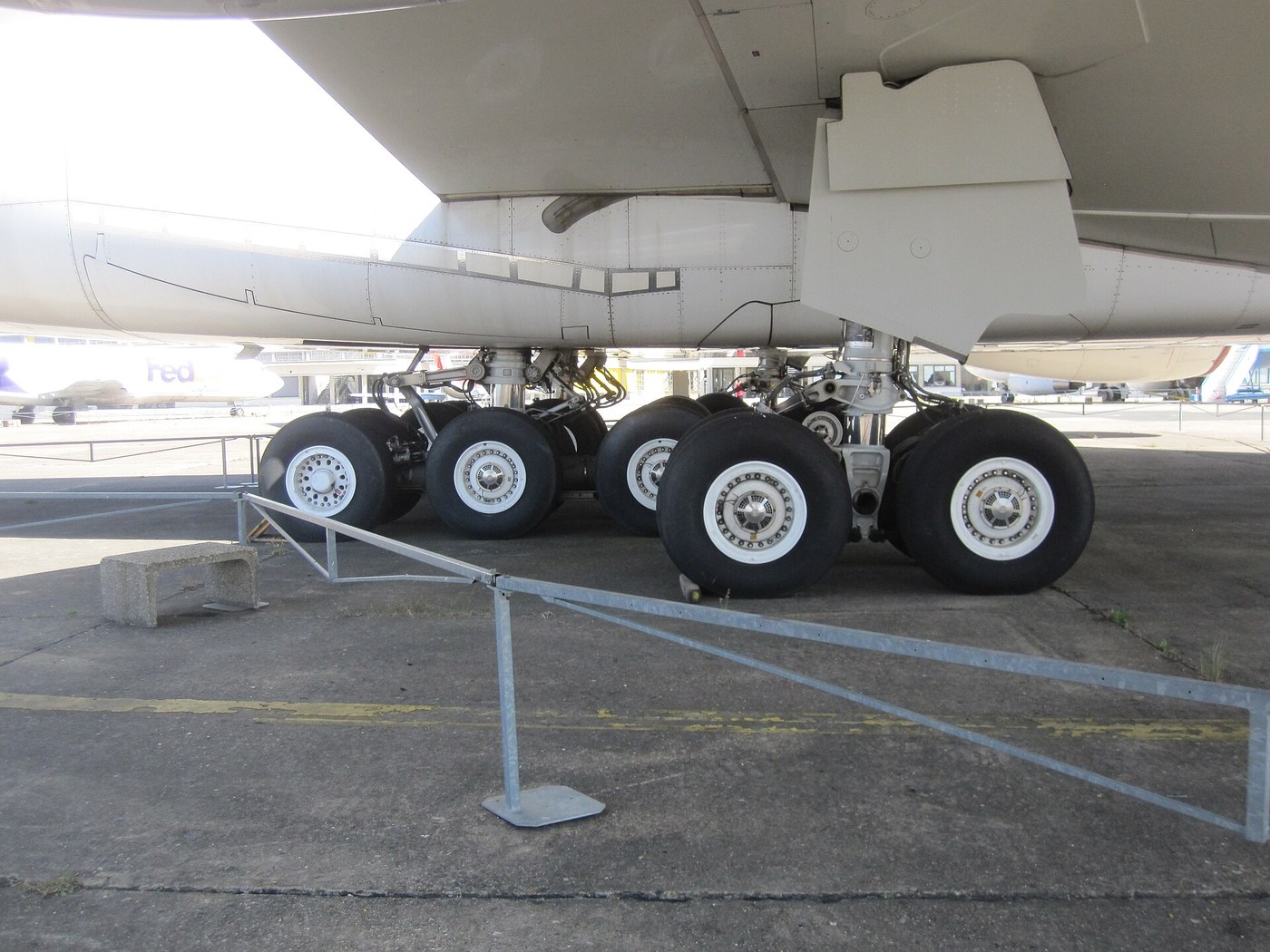


Retractable Landing Gear
دستورالعملها
Measure what the gear costs you
Measure what the gear costs you
Justify the mechanism before building it.
- Mount a model fuselage in the wind tunnel on the drag balance and measure drag with no gear fitted.
- Fit representative fixed gear — two struts, two wheels, a cross brace — and measure again.
- Now fit spatted gear, with streamlined fairings over the wheels, and measure a third time.
Bare struts and wheels add a startling amount of drag; fairings recover a good part of it but never all. A wheel is a bluff body, and a bluff body in an airstream leaves a wide turbulent wake that costs far more than its frontal area suggests.
Spats were the intermediate answer and are still the right one for slow aircraft, where the mechanism’s weight would cost more than the drag it saves. A Piper Cub has fixed gear for the same reason a bicycle has no fairing: below a certain speed, drag is not what limits you. Retraction only pays above roughly 250 km/h, which is exactly when it started appearing.مواد مورد نیاز این مرحله:
 ورق چوب بالسا2 ورق
 ورق چوب نمدار (باسوود)1 ورق
 چسب چوب1 بطری
 کاغذ شطرنجی1 pad
ابزارهای مورد نیاز:
 ارّهنواری (رومیزی)
 مجموعه سوهان
 کولیس دیجیتال ۶ اینچی
 ترازوی فنری
 بادسنج دستی
 عینک ایمنی شفاف
Build the over-centre lock, and feel why it cannot slip
Build the over-centre lock, and feel why it cannot slip
This linkage is the reason retractable gear is trustworthy, and it uses no friction, no catch and no power.
- Make a two-part drag strut: two links joined by a central pivot, the upper anchored to the structure and the lower to the leg.
- Arrange it so that when the gear is down, the central pivot travels slightly PAST the straight line between the two end pivots.
- Fit a light spring that pulls the linkage toward that over-centre position.
- Extend the gear and then try to fold it by pushing up on the wheel.
It will not fold, and the harder you push the more firmly it locks. Once the centre pivot is past the line of the end pivots, a compressive load on the leg produces a moment that drives the knee further over-centre rather than collapsing it. The load holds the lock closed.
Notice what this means: the locking force comes from the aircraft’s own weight, not from an actuator, a spring or a latch. The hydraulic system can fail entirely and the gear stays down. Only a deliberate force applied to break the knee back over centre will unlock it.
The same geometry is everywhere once you know it: toggle clamps, folding table legs, mole grips, the knee joint in your own leg standing straight. It is one of the most useful linkages ever devised and it is worth building purely to feel it engage.مواد مورد نیاز این مرحله:
 تسمهٔ تخت آلومینیومی1 قطعه
 پین فولادی6 قطعه
 مجموعه فنرهای فشاری1 مجموعه
 پیچهای سر استوانهای M56 قطعه
ابزارهای مورد نیاز:
 گیره فرزکاری ۴ اینچ
 دریل ستونیمجموعه سوهانکولیس دیجیتال ۶ اینچی
 ساعت اندازهگیری
 آچار گشتاورسنجعینک ایمنی شفاف
Make it retract into a space that will actually hold it
Make it retract into a space that will actually hold it
The wheel has to end up somewhere, and where it ends up drives the whole aircraft layout.
- Mock up the wing or fuselage bay with the leg attached at its pivot.
- Swing the leg through its full travel and trace the path the wheel sweeps.
- Check for interference with spar, skin and structure at every point in the arc — not just the endpoints.
- Adjust pivot position and leg geometry until the swept path fits.
Checking only the extended and retracted positions is the classic error: the leg can pass through structure at some intermediate angle and be perfectly clear at both ends. Trace the whole arc.
Real designs use rotating legs so the wheel lies flat in a shallow bay, which is why gear legs on many aircraft twist as they fold — that twist is not decoration, it is the only way to fit a round wheel into a thin wing. Landing gear geometry has driven more aircraft layouts than almost any other single component, and it is why a low wing so often has the gear in the wing and a high wing so often has it in the fuselage.مواد مورد نیاز این مرحله:
تسمهٔ تخت آلومینیومی1 قطعهورق چوب نمدار (باسوود)1 ورقپین فولادی4 قطعهابزارهای مورد نیاز:
گیره فرزکاری ۴ اینچدریل ستونیکولیس دیجیتال ۶ اینچی نقاله
نقاله زاویهسنج دیجیتال
 گونیای ترکیبیعینک ایمنی شفاف
Add the emergency extension, and design for the failure
Add the emergency extension, and design for the failure
Assume the power system is dead, and make the gear come down anyway.
- Add a release that disconnects the actuator from the linkage.
- Arrange the geometry so that with the actuator released, gravity alone swings the leg down.
- Confirm the over-centre lock engages under gravity, with a spring assisting if needed.
- Test it repeatedly with the actuator entirely removed.
Free-fall extension is a design requirement, not a nicety, and it constrains the geometry from the beginning. The leg must fold in a direction where gravity helps it extend — which for a wing-mounted leg usually means retracting inboard or rearward, so that dropping it also swings it down and locked.
Aircraft that retract FORWARD exploit this further: with the actuator released, airflow pushes the leg back and down and helps drive it over centre. The airstream becomes the backup actuator.
This is worth generalising: when the powered path fails, ask what forces are still present — gravity, airflow, stored spring energy, the load itself — and arrange the mechanism so those forces produce the safe state. A backup that needs its own power source is a second thing to fail.مواد مورد نیاز این مرحله:
مجموعه فنرهای فشاری1 مجموعهپین فولادی4 قطعهپیچهای سر استوانهای M54 قطعهابزارهای مورد نیاز:
گیره فرزکاری ۴ اینچمجموعه سوهانکولیس دیجیتال ۶ اینچیزاویهسنج دیجیتال گوشی هوشمند با فیلمبرداری آهستهآچار گشتاورسنجعینک ایمنی شفاف
Fit position sensing that reports the lock, not the actuator
Fit position sensing that reports the lock, not the actuator
The indicator must answer the question the pilot is actually asking.
- Fit a microswitch triggered by the ACTUATOR reaching the end of its travel, and wire an indicator to it.
- Now fit a second microswitch triggered by the over-centre LINKAGE reaching its locked position.
- Deliberately jam the linkage just short of over-centre and operate the mechanism.
- Watch both indicators.
The actuator-driven indicator reports gear down; the lock-driven indicator correctly reports that it is not locked. The first one is measuring whether the command was executed. The second measures whether the gear will hold. Those are different questions and only the second one keeps the aeroplane off its belly.
This is why real aircraft sense the downlock itself, usually with three independent switches, and why the classic three green lights mean three legs individually locked rather than one actuator finished.
The general rule is worth carrying into any system: instrument the outcome, not the command. A sensor on the actuator tells you what you asked for. A sensor on the lock tells you what you got. Almost every dangerous instrumentation design confuses the two.مواد مورد نیاز این مرحله:
 ریزکلید (اهرمی)4 قطعه
 مجموعهٔ الایدی نشانگر1 مجموعه
 سیم اتصال1 reel
ابزارهای مورد نیاز:
دریل ستونیمجموعه سوهانکولیس دیجیتال ۶ اینچیعینک ایمنی شفافمواد
11- 2 ورقجایگزین
- جایگزین
- 1 بطریجایگزین
- 1 padجایگزین
- 1 قطعهجایگزین
- 14 قطعهجایگزین
- 1 مجموعهجایگزین
- 10 قطعهجایگزین
- 4 قطعهجایگزین
- 1 مجموعهجایگزین
- 1 reelجایگزین
ابزارهای لازم
14- جایگزین
- جایگزین
- جایگزین
- جایگزین
- جایگزین
- جایگزین
- جایگزین
- جایگزین
- جایگزین
- جایگزین
- جایگزین
- جایگزین
- جایگزین
نقشههای مرتبط
این نقشهها دانش مشترکی دارند — تکنیکها، مواد یا اصول

CC0 مالکیت عمومی
این نقشه تحت مجوز CC0 منتشر شده است. شما آزاد هستید آن را کپی، ویرایش، توزیع و برای هر هدفی بدون نیاز به اجازه استفاده کنید.
با خرید محصولات از طریق نقشه از سازنده حمایت کنید و او کمیسیون سازنده تعیین شده توسط فروشندگان، دریافت میکند یا یک نسخه جدید از این نقشه ایجاد کنید و آن را به عنوان اتصال در نقشه خود قرار دهید تا درآمد به اشتراک گذاشته شود.