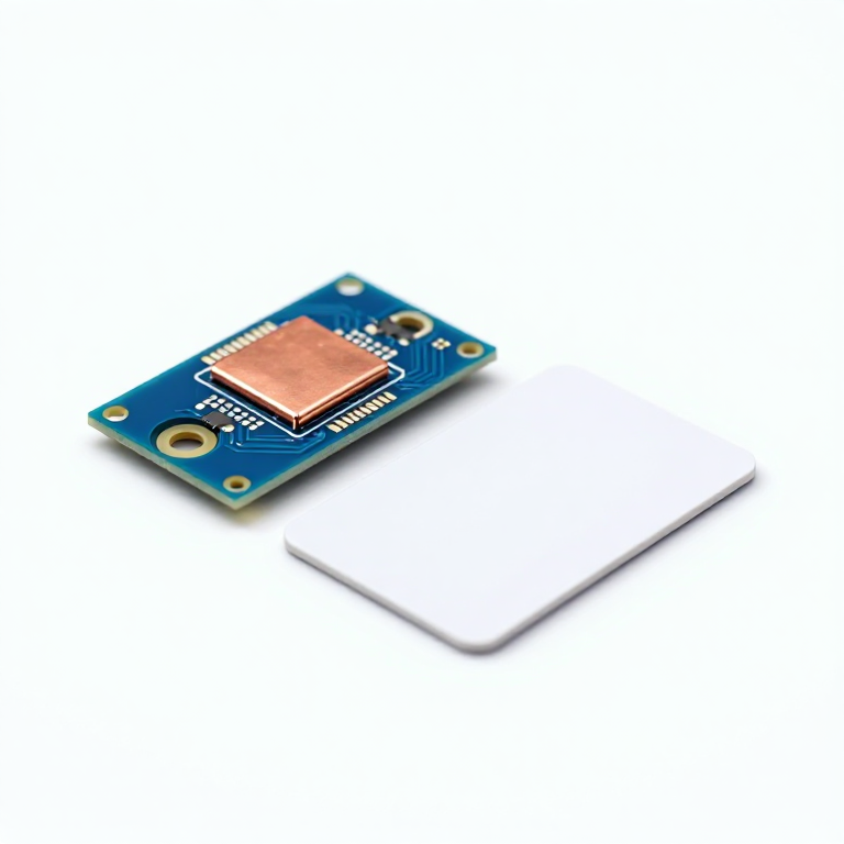


RFID Access Reader
دستورالعملها
Assemble the relay board
Assemble the relay board
The Beefcake board ships as a kit and has to be soldered before anything else.
- Fit the relay, the screw terminals and the passives.
- Check the coil side and the contact side are on the correct halves of the board before applying power.
مواد مورد نیاز این مرحله:
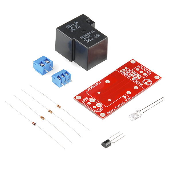 SparkFun Beefcake Relay Control Kit1 کیت
ابزارهای مورد نیاز:
 Ryobi ONE+ RSI18-0 Cordless Soldering Iron
Mount the reader module and wire it — pin by pin
Mount the reader module and wire it — pin by pin
Fit the SM130 and its antenna to the 13.56 MHz evaluation shield, then wire the shield to the Arduino.
- SM130 TX → Arduino D2 (Arduino receives)
- SM130 RX → Arduino D3 (Arduino transmits)
- SM130 VCC → 5V, GND → GND
- Relay board control input → Arduino D7, its GND to Arduino GND
The SM130's UART is 5 V and 5 V tolerant, so it connects straight to an Uno with no level converter. That is specific to this module — the 3.3 V SM5210 parts do need one.
Never wire the module's UART pins to an RS232 port directly. RS232 swings around ±12 V and will destroy it; a USB-UART adapter is required.مواد مورد نیاز این مرحله:
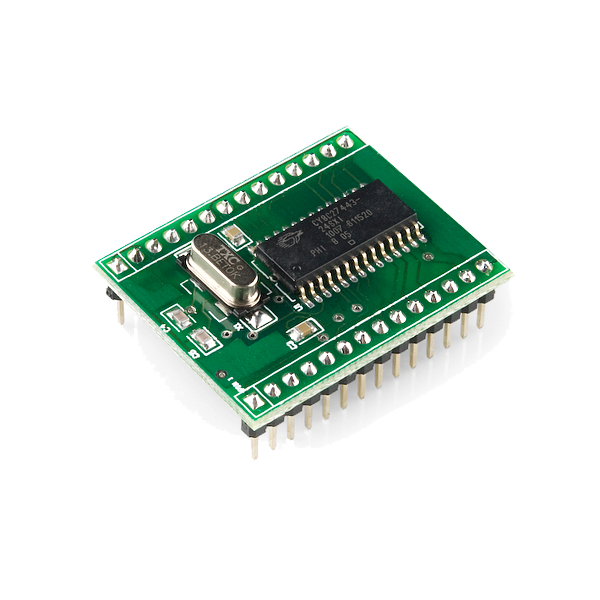 RFID Module - SM130 Mifare (13.56 MHz)1 قطعه
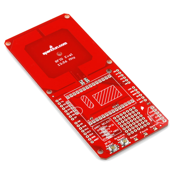 RFID Evaluation Shield - 13.56MHz1 قطعه
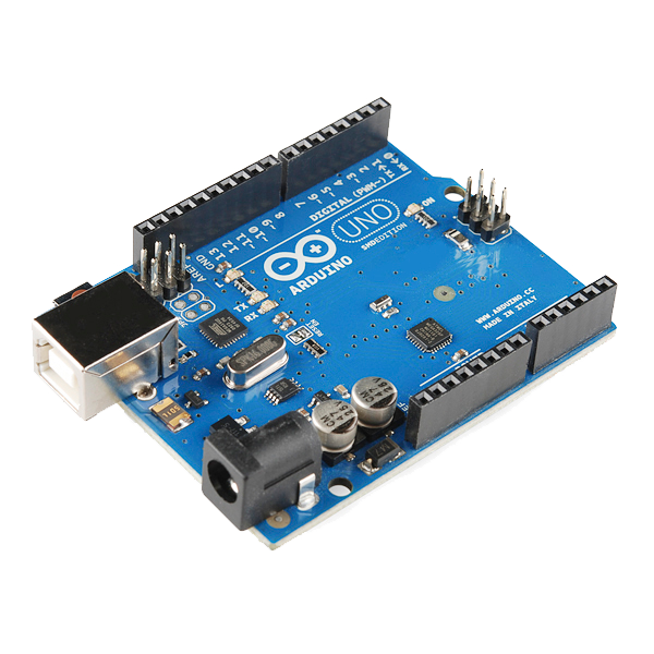 Arduino Uno R3 SMD1 قطعه
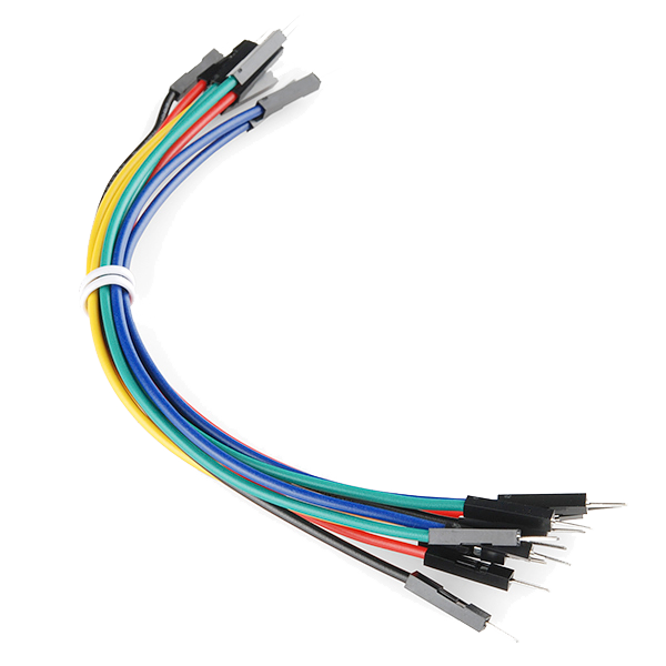 Jumper Wires Premium M/M 20 AWG - 15.5 cm (Pack of 10)1 بسته
Configure the module for Auto Mode with ASCII output
Configure the module for Auto Mode with ASCII output
Out of the box the module is in Standard Mode, where it waits for binary commands. Put it into Auto Mode with ASCII output instead, using SonMicro's Mifare Panel tool over a USB-UART adapter.
- Set Operation Mode to Auto Mode (Automatic Card Reading).
- Under Auto Read Mode set Serial Output Type to ASCII, and tick CR and LF.
- Leave Baudrate at its factory 19200.
That combination is the stock template 02/AUTO-B-P-ASCII-CRLF, so it can also be ordered pre-configured, or applied from a supplied .xml upgrade file with no configuration step at all.
Auto Mode is what makes this project simple. The module reports each card as a line of plain text the moment it enters the field, so the Arduino never has to build a framed binary packet or verify a checksum.مواد مورد نیاز این مرحله:
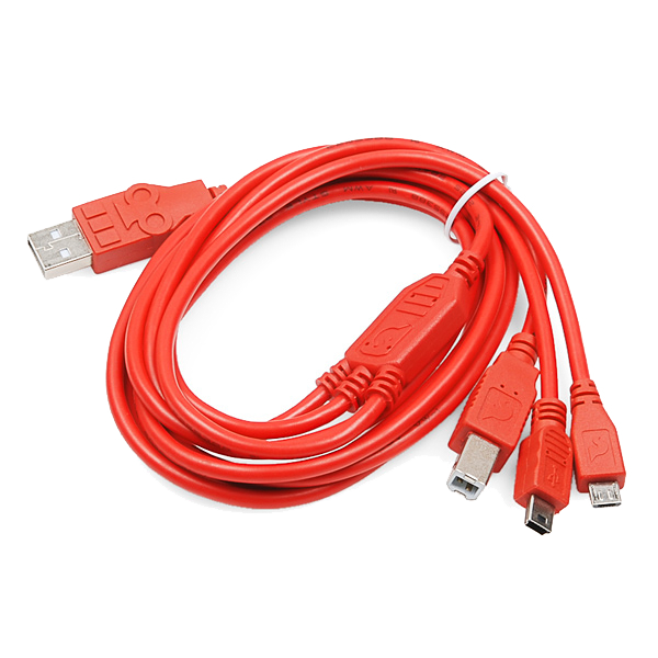 USB-B Cable1 قطعه
Read a card and write its identifier down
Read a card and write its identifier down
Power the Arduino over USB, open the serial monitor at 9600, and upload the sketch from the next step with the allow-list still empty.
- Present a tag. A line of hex digits appears.
- Write that identifier down exactly as printed.
- Repeat for every card that should be allowed.
مواد مورد نیاز این مرحله:
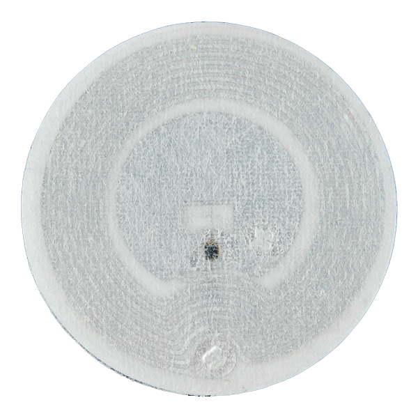 RFID Tag - Adhesive Mifare 1K (13.56 MHz)2 قطعه
Upload the access sketch
Upload the access sketch
Put the identifiers you recorded into the ALLOWED array, then upload. SoftwareSerial ships with the IDE — nothing else is needed.
Test the reject path before the accept path
Test the reject path before the accept path
Present an unlisted card first, and confirm the relay stays shut and the monitor prints denied.
- Only then present a listed card and confirm it opens.
- Wire the strike through the relay's normally-open contact, so a power cut leaves the door secure rather than released.
مواد
7- SparkFun Beefcake Relay Control Kit10% کمیسیون1 کیت$7.49
- RFID Module - SM130 Mifare (13.56 MHz)10% کمیسیون1 قطعه$26.85
- RFID Evaluation Shield - 13.56MHz10% کمیسیون1 قطعه$19.28
- Arduino Uno R3 SMD10% کمیسیون1 قطعه$26.85
- 1 بسته$4.97
- SparkFun Cerberus USB Cable - 1.8 meter10% کمیسیون1 قطعه$5.64
- RFID Tag - Adhesive Mifare 1K (13.56 MHz)10% کمیسیون2 قطعه$3.54
ابزارهای لازم
1- $92.47
CC0 مالکیت عمومی
این نقشه تحت مجوز CC0 منتشر شده است. شما آزاد هستید آن را کپی، ویرایش، توزیع و برای هر هدفی بدون نیاز به اجازه استفاده کنید.
با خرید محصولات از طریق نقشه از سازنده حمایت کنید و او کمیسیون سازنده تعیین شده توسط فروشندگان، دریافت میکند یا یک نسخه جدید از این نقشه ایجاد کنید و آن را به عنوان اتصال در نقشه خود قرار دهید تا درآمد به اشتراک گذاشته شود.