Driving an RGB LED — SIK Circuit 3
دستورالعملها
Parts & Introduction
Parts & Introduction
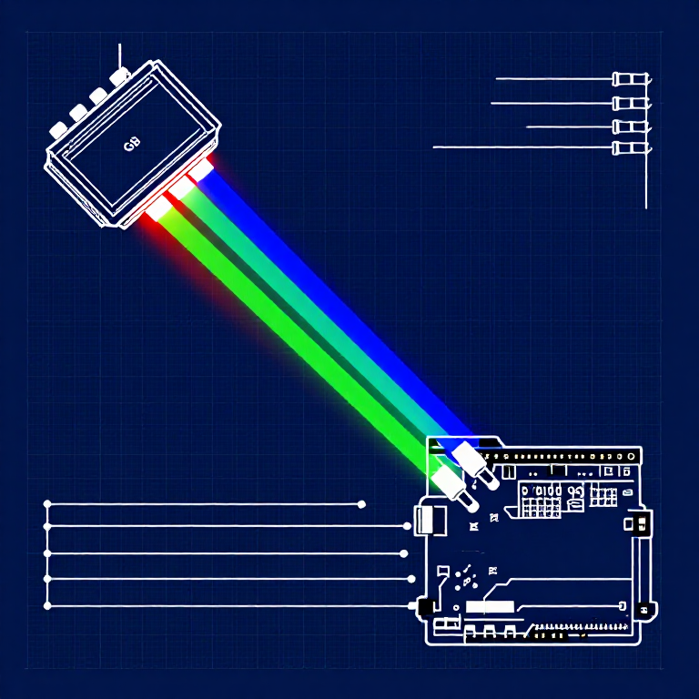
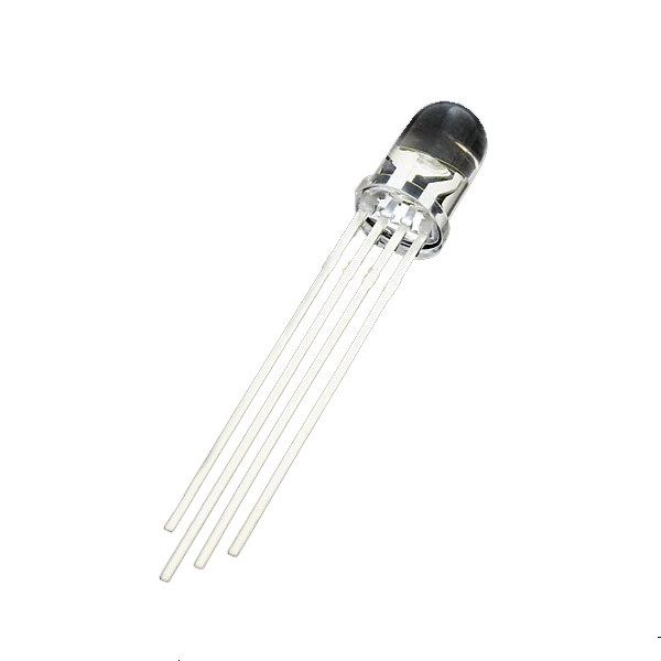
An RGB LED contains three tiny LEDs (red, green, blue) in one package. By mixing different brightness levels of each color, you can create any color in the rainbow. This experiment introduces analogWrite() for PWM output.
Parts Needed
- 1x Arduino Uno + USB cable
- 1x Breadboard
- 1x RGB LED (Common Cathode)
- 3x 330Ω Resistors
- 5x Jumper Wires
RGB LED Pin Order (flat edge facing you): Red, Ground (longest pin), Green, Blue.
مواد مورد نیاز این مرحله:
 SparkFun Inventors Kit - V3.21 kit
 Arduino Uno R31 piece
 Breadboard1 piece
 RGB LED (Common Cathode)1 piece
 330 Ohm Resistor3 pieces
 Jumper Wires5 pieces
ابزارهای مورد نیاز:
Hardware Hookup
Hardware Hookup
Wiring Instructions
- Place the RGB LED in the breadboard. Identify pins from the flattened edge: Red, GND (longest), Green, Blue.
- Connect the GND pin (longest, second from left) to the GND rail.
- Connect the Red pin through a 330Ω resistor to Arduino Pin 9.
- Connect the Green pin through a 330Ω resistor to Arduino Pin 10.
- Connect the Blue pin through a 330Ω resistor to Arduino Pin 11.
Pins 9, 10, and 11 are all PWM-capable (marked with ~ on the board).
مواد مورد نیاز این مرحله:
RGB LED (Common Cathode)1 piece330 Ohm Resistor3 piecesBreadboard1 pieceJumper Wires5 piecesArduino Code
Arduino Code
Open the Arduino IDE and upload the following sketch to your Arduino board.
مواد مورد نیاز این مرحله:
Arduino Uno R31 pieceابزارهای مورد نیاز:
Test & Experiment
Test & Experiment
What You Should See
The LED cycles through 8 solid colors (off, red, green, blue, yellow, cyan, purple, white) for 1 second each, then smoothly fades through the entire color spectrum.
Troubleshooting
- Incorrect colors: With four pins close together, it's easy to misplace one. Double-check each connection.
- Red too bright: The red diode is often brighter. Try a higher-value resistor on the red pin, or reduce in code:
analogWrite(RED_PIN, redIntensity/3).
Experiments to Try
- Add a potentiometer to control which color is displayed.
- Create your own color sequences — try a "sunrise" effect (dark red → orange → yellow → white).
مواد
6- $105.00
- 1 pieceجایگزین
- 1 pieceجایگزین
- جایگزین
- $3.00
Required Equipment
Equipment this kind of build typically needs — buy from any maker below.
- CriticalSoldering Iron·
 Helping Hands Soldering Stand
 Solder Tip Tinner and Cleaner
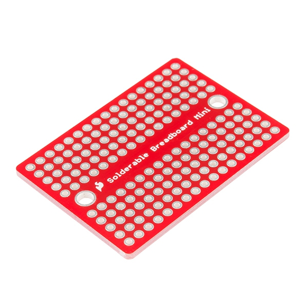 SparkFun Solder-able Breadboard - Mini
 Soldering Iron
 Solder Wire
 Soldering Flux Paste (50g, Rosin-Based)
 - RecommendedBreadboard·
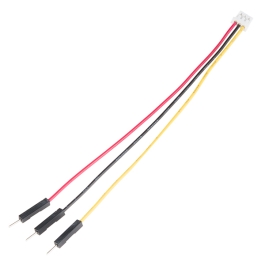 JST to Breadboard Jumper (3-pin)
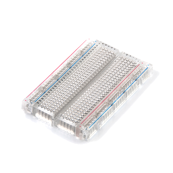 Breadboard - Translucent Self-Adhesive (Clear)Solderless Breadboard 830 Points (3-Pack)SparkFun Solder-able Breadboard - Mini
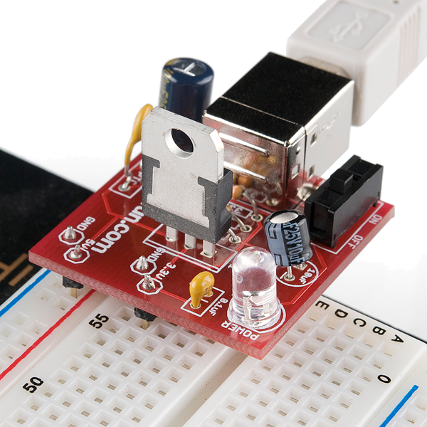 Breadboard Power Supply USB - 5V/3.3VBreadboard
 - RecommendedDust Mask / Respirator·
 Full-Face Gas Mask (ABEK multi-gas cartridge)
 Dust Mask
 Venetian Mask Blank (Papier-Mache)
 Full-Face Respirator
 Respirator Fit Test Kit
 Respirator with Acid Gas Cartridge
 - RecommendedMultimeter·
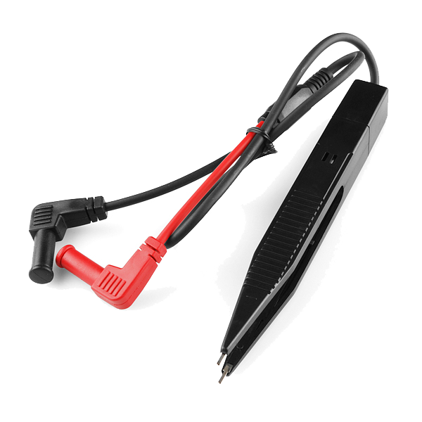 Multimeter Tweezer Probes
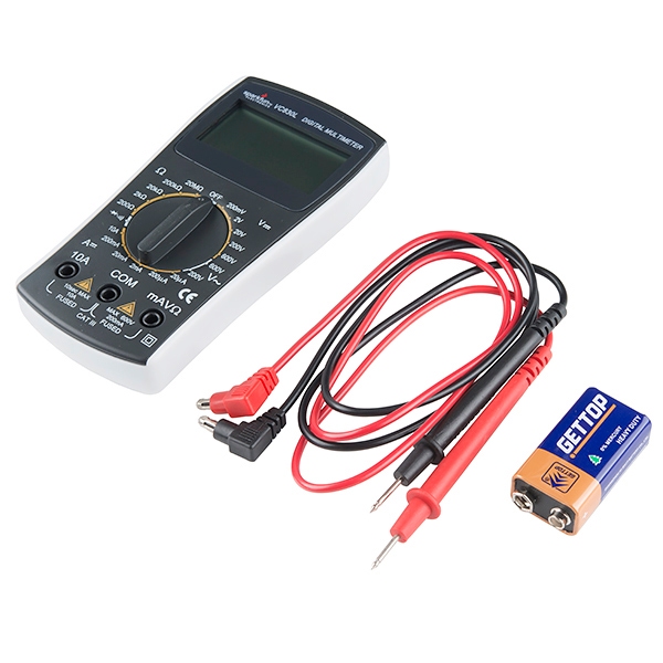 Digital Multimeter - Basic
 Digital Multimeter Pro
 Multimeter
 Digital Multimeter (Auto-Range, True RMS)Digital Multimeter
 - RecommendedSafety Glasses·
 Safety Sign (Caution/Warning)
 Splash-Proof Safety Goggles
 Reflective Safety Vest Kit (DIY)
 Chemical Splash Goggles
 Safety Netting for Rockfall
 Steel-Toed Safety Boots
 - RecommendedWire Strippers·
 Wire Strippers
 Wire Stripper & Crimping Tool (AWG 10-22)
 Wire Stripper
 - RecommendedWork Gloves·
 Boxing Gloves (Training)
 Leather Gauntlet Gloves
 Cotton Gloves
 Welding Gloves
 Heavy-Duty Gloves
 Leather Work Gloves
 - OptionalFire Extinguisher·
 ABC Fire Extinguisher
 Fire Extinguisher
 - OptionalFirst Aid Kit·
 First Aid Kit
 Mountain First Aid Kit (Altitude)
 Workshop First Aid Kit
 Bow Release Aid
 - OptionalHelping Hands / Third Hand·Helping Hands Soldering Stand
 Helping Hands
 PCB Holder Helping Hands (with Magnifier)
 Helping Hands (Third Hand)
You can swap these in
Can't get one of the materials? Swap it for an equivalent — these work just as well.
- Instead of Arduino Uno R3, try:
 Prototyping Shield for Arduino Uno (3-Pack)
 Arduino Uno R3 BoardArduino Uno
 - Instead of Resistor 330 Ohm 1/6 Watt PTH - 20 pack, try:
 Resistor 10K Ohm 1/6th Watt PTH - 20 pack
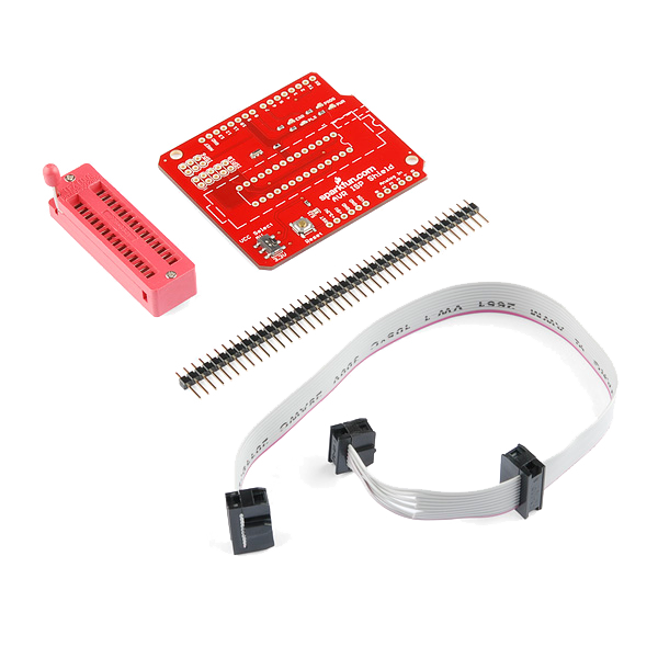 AVR ISP Shield - PTH Kit
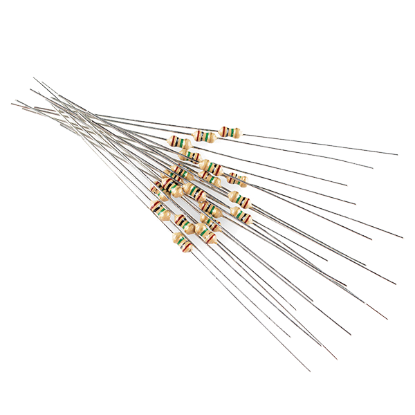 Resistor 1.0M Ohm 1/6th Watt PTH - 20 pack
 - Instead of Breadboard, try:
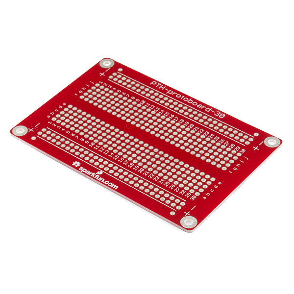 Solder-able Breadboard
 - Instead of LED - RGB Diffused Common Cathode - 5mm, try:
 LED - RGB Clear Common Cathode - 5mm
Recommended for this build
Products makers often use with builds like this one.
 5mm LED Assortment Kit (300pcs, 5 Colors)Used together and in similar buildsResistor 10K Ohm 1/6th Watt PTH - 20 packFrequently used with this build's materials
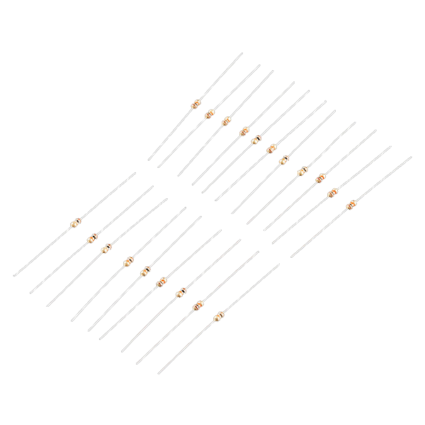
 Diode KitFrequently used with this build's materials
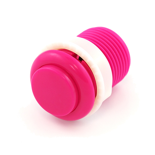 Push Button - 33mmFrequently used with this build's materials
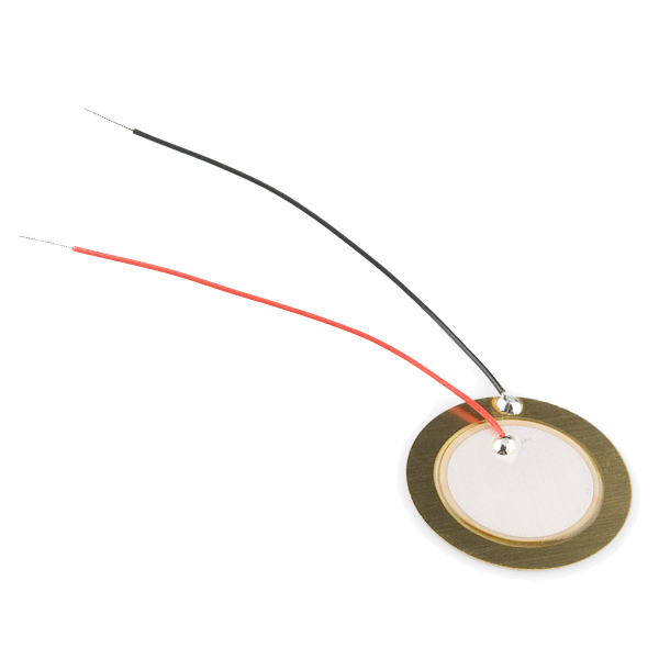 Piezo ElementFrequently used with this build's materials
 PotentiometerFrequently used with this build's materials
 Servo MotorFrequently used with this build's materials
Related blueprints
Other builds that share materials, tools, or techniques with this one.

CC0 مالکیت عمومی
این نقشه تحت مجوز CC0 منتشر شده است. شما آزاد هستید آن را کپی، ویرایش، توزیع و برای هر هدفی بدون نیاز به اجازه استفاده کنید.
با خرید محصولات از طریق نقشه از سازنده حمایت کنید و او کمیسیون سازنده تعیین شده توسط فروشندگان، دریافت میکند یا یک نسخه جدید از این نقشه ایجاد کنید و آن را به عنوان اتصال در نقشه خود قرار دهید تا درآمد به اشتراک گذاشته شود.