LIST
FEGURÐ OG VELLÍÐAN
HANDVERK
MENNING OG SAGA
SKEMMTUN
UMHVERFI
MATUR OG DRYKKUR
ÖFUGVERKFRÆÐI
VÍSINDI
ÍÞRÓTTIR
TÆKNI
KLÆÐANLEG TÆKNI
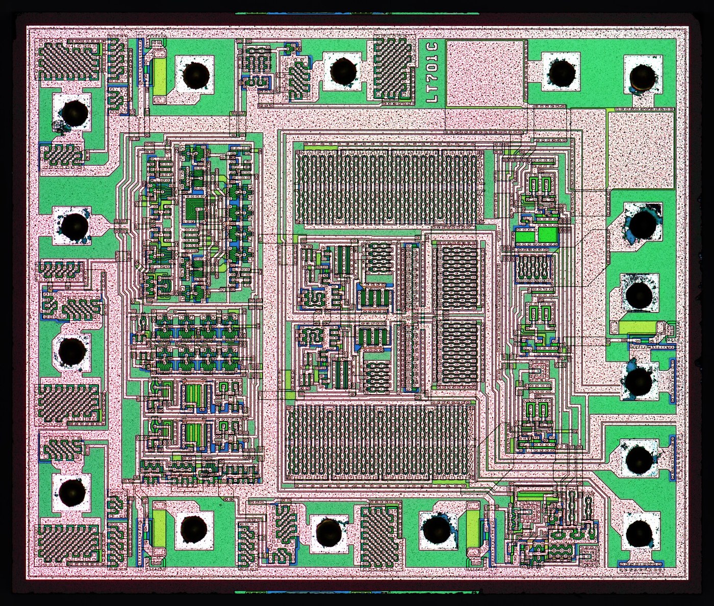


The Phase-Locked Loop
Every loop so far feeds back an amplitude - a voltage, an angle, a speed - and settles when the correction balances the error, which means a little error always remains. Henri de Bellescize's synchronous receiver of 1932 feeds back something else: the PHASE difference between an incoming signal and a local oscillator.
That one change buys a property no amplitude loop can offer. Frequency is the rate of change of phase, so an oscillator is already an integrator. Hold the phase error at any constant value and the two frequencies must be EXACTLY equal - not close, equal to the last decimal place - for as long as the lock holds. The remaining error is pushed entirely into the phase, which sits wherever it must to keep the oscillator pulled to the right frequency.
Three blocks do it. A phase detector, which is a multiplier; a loop filter, which decides the dynamics; and a voltage-controlled oscillator, which is the plant. The filter's time constant sets a trade you cannot avoid: a narrow loop rejects noise and rides through a dropout but takes a long time to acquire, and a wide loop locks instantly and passes the noise straight onto the recovered clock.
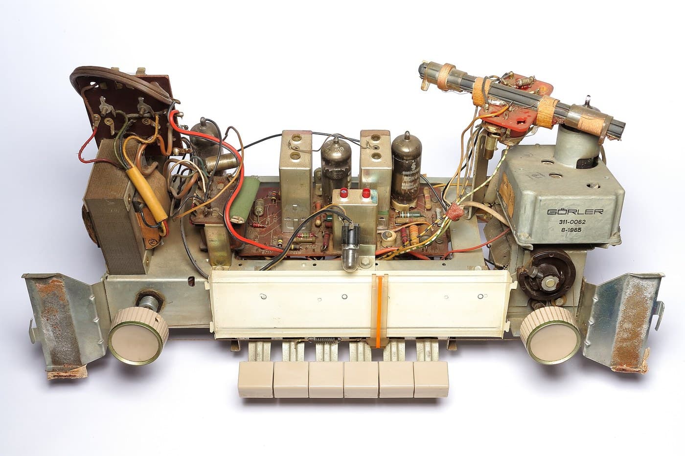
It is worth seeing this next to the regenerative receiver, because they are the same circuit pushed in opposite directions. Regeneration uses positive feedback and is set as close to oscillating as the operator dares. A phase-locked loop lets its oscillator run freely and uses negative feedback to drag it into step with something outside. One asks a human to hold a circuit on the edge of instability; the other never goes near it - which is why a locked receiver can be sealed in a box and forgotten.
Lengra kominn
3 hours
Leiðbeiningar
1
1
A VCO and a phase detector
A VCO and a phase detector
Wire a 555 as an astable near 5 kHz and bring its control pin out - that pin is a voltage-controlled oscillator, and a few hundred millivolts on it swings the frequency by a good fraction.
Feed the 555 output and a signal from the generator into an XOR gate. Its average output voltage is the phase difference, which you can see on a meter as you sweep the generator past the 555's free-running frequency.
Efni fyrir þetta skref:
 NE555 tímarás1 pakki
 Úrval rökrása1 sett
 Viðnámasett 1/4 W1 sett
 Sett af keramikþéttum1 sett
Nauðsynleg verkfæri:
 Tengibretti
 DDS-merkjagjafi
 Stafrænt sveiflusjá
 Stafrænn margmælir í rannsóknastofugæðum
2
2
Close the loop and find the edges of lock
Close the loop and find the edges of lock
Filter the XOR output with a 10k and 1 uF and take it to the 555's control pin. Sweep the generator slowly: at some point the 555 snaps into step and stays there while you keep tuning.
Note the two frequencies where it grabs and the two where it lets go. The capture range is narrower than the hold range, and swapping the capacitor for 100 nF changes both - that is the loop filter setting the dynamics.
Efni fyrir þetta skref:
 Rafgreiningarþéttasett1 settViðnámasett 1/4 W1 sett
Nauðsynleg verkfæri:
TengibrettiDDS-merkjagjafiStafrænt sveiflusjáStafrænn margmælir í rannsóknastofugæðum3
3
Lock range, loop dynamics, and four receivers
Lock range, loop dynamics, and four receivers
Hleð Jupyter-vinnubók…
Nauðsynleg verkfæri:
 Borðtölva
4
4
Compendium: locking to the wrong thing
Compendium: locking to the wrong thing
A phase detector made from a multiplier or an XOR cannot tell a signal from its harmonics, so a loop free-running near 5 kHz will happily lock to a 2.5 kHz input at twice the rate, or to 15 kHz at a third. In a laboratory that is a puzzle; in a receiver it is a wrong station. The cures are all about restricting where the oscillator is allowed to be before the loop is closed - a narrow VCO tuning range, a coarse frequency detector that steers the loop into the right region first, or a phase-frequency detector, which uses two flip-flops to report which signal is AHEAD rather than merely how far apart they are, and so cannot be fooled by a harmonic at all.
Capture range and hold range are different numbers, and the experiment shows it. Once locked, the loop holds until the phase error runs out of room - the full loop gain. Unlocked, the detector output is a beat note the filter mostly throws away, so the loop only pulls itself in from a much narrower band. Every PLL therefore has a region where it stays locked if it already is and never finds lock on its own, which is why synthesisers carry a lock detector and a sweep circuit.
Efni
5- 1 pakkiStaðgengill
- 1 settStaðgengill
- 1 settStaðgengill
- 1 settStaðgengill
- 1 settStaðgengill
Tengd Blueprint
Þessi blueprint deila þekkingu — tækni, efni eða meginreglur

CC0 opinbert ríki
Þessi teikning er gefin út undir CC0. Þér er frjálst að afrita, breyta, dreifa og nota þetta verk í hvaða tilgangi sem er, án þess að biðja um leyfi.
Studdu smiðinn með því að kaupa vörur í gegnum teikningu hans þar sem hann fær þóknun smiða sem seljendur ákvarða, eða búðu til nýja endurskoðun á þessari teikningu og tengdu hana sem tengingu í þinni eigin teikningu til að deila tekjum.