LIST
FEGURÐ OG VELLÍÐAN
HANDVERK
MENNING OG SAGA
SKEMMTUN
UMHVERFI
MATUR OG DRYKKUR
ÖFUGVERKFRÆÐI
VÍSINDI
ÍÞRÓTTIR
TÆKNI
KLÆÐANLEG TÆKNI
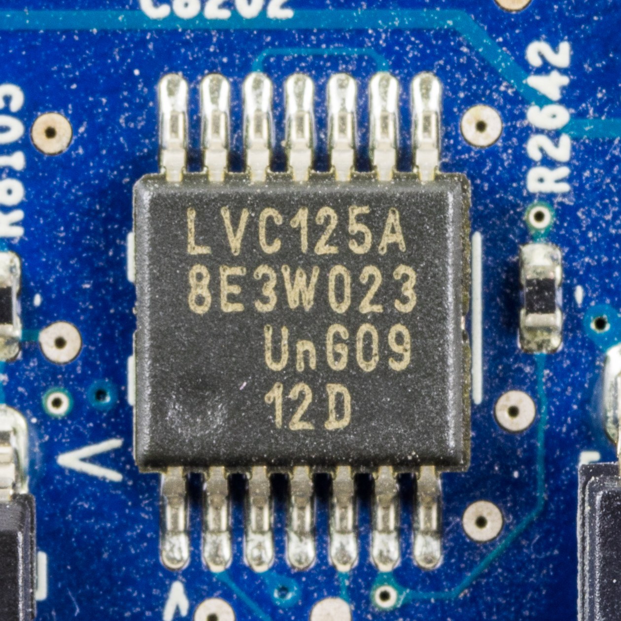


Surface Mount and the Gull Wing
This is the sibling of `lead-frame-dip-package`. Same job — fan a die's connections out to something a board can use, seal it, and conduct its heat away — and one change that follows from a single decision: do not put the leads through the board.
A DIP's leads go through drilled holes and are soldered on the far side. That means every pin needs a hole, holes cost money and board area, a hole occupies BOTH sides of the board so nothing can sit opposite, and the lead has to be long enough to reach through.
Surface mount stops at the surface. The lead is bent out and down into a shallow foot that sits ON a pad, and solder paste printed onto that pad is melted to make the joint. No hole, no far side, no long lead.
Every advantage falls out of that. Both sides of the board become usable, which halves the area at a stroke. Leads can go on all four edges instead of two, so pin count is no longer proportional to package length. The leads are one to two millimetres instead of six to fifteen, which cuts inductance by the same factor and is what let clock rates rise. And assembly becomes a machine placing parts on paste rather than a machine pushing pins through holes, which is faster and works for parts far too small to have pins at all.
The classic lead shape is the GULL WING: out from the body, down, then flat. It is named for what it looks like end-on and it is a compromise. The horizontal foot gives a solderable, INSPECTABLE joint you can see and probe. The bend gives compliance, which the joint badly needs, because unlike a through-hole lead the solder joint is now the only thing holding the part on AND the only thing absorbing the expansion mismatch between package and board.
That last point is the whole reliability story of surface mount, and it is why this blueprint spends its measurement effort on thermal cycling rather than on soldering.
Miðlungs
6 hours
Leiðbeiningar
1
1
Reflow solder a board, and cycle it until the joints fail
Reflow solder a board, and cycle it until the joints fail
Surface mount is assembled by printing solder paste, placing parts on it, and heating the whole board through a profile. Reproduce that, then attack the result.
PRINT THE PASTE. A stencil is a thin steel or polyimide sheet with apertures over each pad. You can cut one from 100 micrometre polyimide with a craft knife for a coarse footprint, or buy one, or simply dispense paste from a syringe onto each pad. Aim for a consistent volume — the joint's strength and its stand-off both depend on it, and inconsistent paste is the commonest cause of a bad hand-reflowed board.
PLACE THE PARTS with tweezers. Precision is less critical than people expect, because of a genuinely useful effect: molten solder's surface tension pulls a slightly misplaced part into alignment with its pads. A part placed within a third of a pad width will usually self-centre. That self-alignment is one of the quiet reasons surface mount scaled to machine assembly at all.
REFLOW IT. A hotplate works for a small board, or a modified toaster oven, or a proper reflow plate. The profile matters and has four phases: preheat to about 150 degrees to bring everything up evenly, soak at 150 to 180 for a minute or two to activate the flux and let the board equalise, ramp to peak — around 240 for lead-free, 215 for leaded — for 30 to 60 seconds above the melting point, then cool.
WATCH IT REFLOW. There is a distinct moment where the paste goes from dull grey to bright and liquid, and parts visibly twitch into alignment. That moment is the process; everything before it is preparation and everything after is cooling.
INSPECT THE FILLETS. A good gull-wing joint has a concave fillet that wets up the side of the lead. Too little paste gives a thin joint with no fillet; too much gives a bulging joint and risks bridging to the neighbour. Photograph them under the microscope — and note that you CAN photograph them, which you could not do with a J-lead or a BGA.
NOW THE MEASUREMENT THAT MATTERS. Wire the board so you can measure continuity through a chain of joints — a daisy chain through every pin of a part, which is exactly what test coupons do in industry.
Thermal cycle it. Between a domestic freezer and an oven at 100 degrees, twenty minutes each way, and measure the chain resistance every ten cycles. Or use a hotplate and a fan for faster, smaller cycles.
The resistance rises before anything opens. A solder joint under cyclic strain accumulates fatigue cracks, and a partially cracked joint is a higher-resistance joint long before it is an open one. Plot resistance against cycle count and you get a curve that is flat, then rises, then goes open — the same shape as flash endurance and the same shape as die-attach delamination, from a completely different mechanism.
That is why through-hole survives in high-vibration and high-cycling applications: a through-hole lead is mechanically anchored by the board itself, and its solder joint is not the only thing holding it on.
Efni fyrir þetta skref:
 Lóðmálmsmauk (blýlaust)1 stykki
 Óáletruð prentplata (koparhúðuð)4 stykki
 Pólýimíðfilma1 stykki
 Tengivír5 metre
Nauðsynleg verkfæri:
 Hitaplata með seglhræru
 Stafræn smásjá
 Nákvæmnispinsettusett
 Stafrænn margmælir í rannsóknastofugæðum
 Innrauður hitamælir
 Föndurhnífur
 Ísóprópanól 99 %
 SOIC-prófunaríhlutir
2
2
Area, inductance and fatigue — the three-way trade
Area, inductance and fatigue — the three-way trade
Hleð Jupyter-vinnubók…
Nauðsynleg verkfæri:
 Borðtölva
Efni
4- 1 stykkiStaðgengill
- 4 stykkiStaðgengill
- 1 stykkiStaðgengill
Nauðsynleg verkfæri
9- Staðgengill
- Staðgengill
- Staðgengill
- Staðgengill
- Staðgengill
- Staðgengill
- Staðgengill
- Staðgengill
- Staðgengill
Tengd Blueprint
Þessi blueprint deila þekkingu — tækni, efni eða meginreglur

CC0 opinbert ríki
Þessi teikning er gefin út undir CC0. Þér er frjálst að afrita, breyta, dreifa og nota þetta verk í hvaða tilgangi sem er, án þess að biðja um leyfi.
Studdu smiðinn með því að kaupa vörur í gegnum teikningu hans þar sem hann fær þóknun smiða sem seljendur ákvarða, eða búðu til nýja endurskoðun á þessari teikningu og tengdu hana sem tengingu í þinni eigin teikningu til að deila tekjum.