Collaborazione
ARTE
BELLEZZA E BENESSERE
MESTIERE
CULTURA E STORIA
DIVERTIMENTO
AMBIENTE
CIBO E BEVANDE
INGEGNERIA INVERSA
SCIENZE
SPORT
TECNOLOGIA
INDOSSABILI
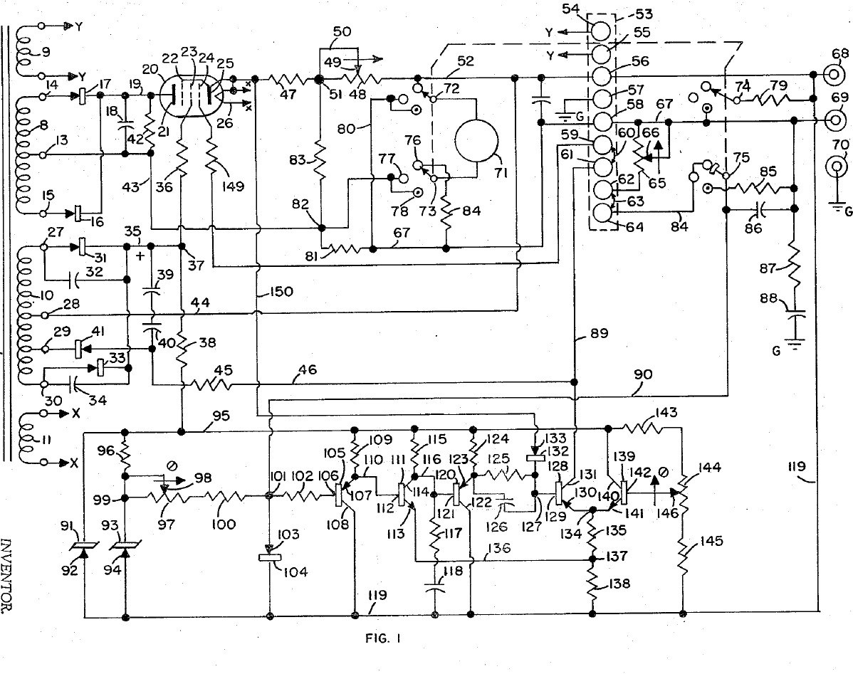


Bench Power Supply: Regulated, with Adjustable Current Limit and a Pentode Pass Tube (Gately, Forbro, US 3,243,690, 1966)
An adjustable bench supply that holds its output voltage steady and lets you set the most current it will deliver, so a circuit under test cannot be damaged. A pentode tube in series with the output is the regulator; a bridge with Zener references and a five-transistor amplifier keeps the output equal to the setting of one knob. A meter switch reads volts, amps, and the current limit, which can be set without disturbing the voltage.
Result: a regulated DC bench supply with adjustable current limiting.
Source: J. R. Gately (Forbro Design), US 3,243,690 (1966). Unknown: all component values and the output rating. Picture: the patent drawing.
Avanzato
Unknown
Istruzioni
1
1
Wire the mains side
Wire the mains side
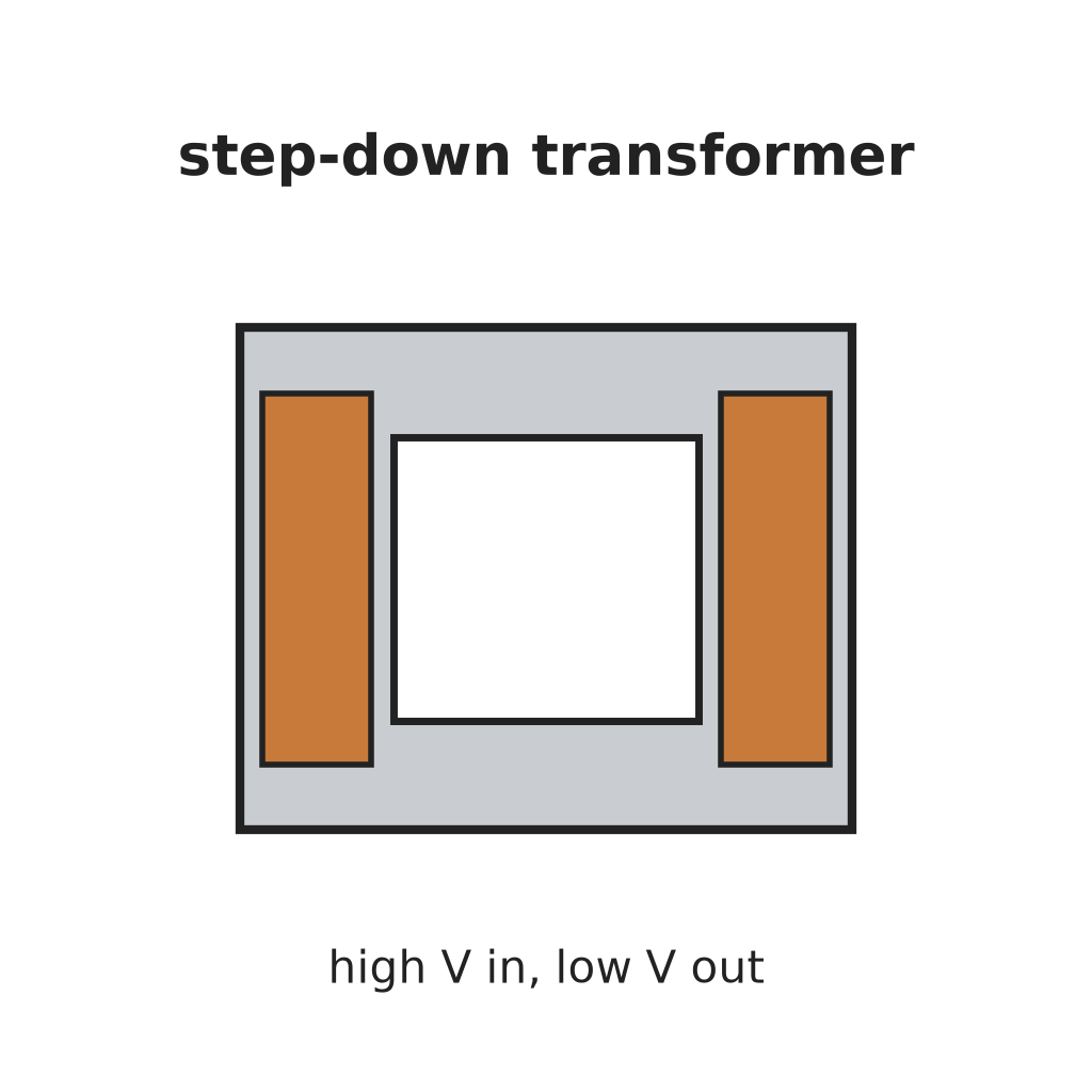
In a case, wire the power cord through a switch and a fuse to the primary of a transformer with four secondaries, and put a neon lamp across the primary to show the supply is on. One secondary (6.3 V) goes to two terminals for outside use, one heats the pentode, one is the main supply and one the bias supply. Ours: the case. Not given: the other winding voltages.
Materiali per questo passaggio:
 Contenitore in alluminio1 case
 Cavo flessibile con spina1 pezzo
 Interruttore a levetta1 pezzo
 Fusibile1 pezzo
 Trasformatore riduttore1 four secondaries
 Lampada spia al neon1 pezzo
 Boccola da pannello2 6.3 V terminals
Strumenti necessari:
 Trapano a mano
 Set di cacciaviti
2
2
Build the rectifiers
Build the rectifiers
Rectify the centre-tapped main winding with two rectifiers and smooth it with a capacitor. From the bias winding make two more supplies: one through two rectifiers with by-pass capacitors to a smoothing capacitor, for the pentode's screen and the reference circuit; the other through one rectifier and a capacitor, for the pentode's grid bias. Not given: the values.
Materiali per questo passaggio:
 Diodo5 rectifiers
 Condensatore elettrolitico3 smoothing
 Kit di condensatori1 by-pass
 Filo per saldatura1 as needed
Strumenti necessari:
 Saldatore a stagno
3
3
Fit the pass tube and reference
Fit the pass tube and reference
Put the pentode in series with the positive output: plate to the main supply, cathode through two current-sensing resistors (one fixed, one adjustable) to the + output terminal; suppressor tied to the cathode, screen fed through a resistor. Build the reference: a Zener fed through a resistor feeds a second Zener at constant current, giving a fixed voltage. Against it set two resistors and the voltage-control variable resistor: the output voltage is proportional to that resistor's setting. Not given: the tube type and values.
Materiali per questo passaggio:
 Valvola pentodo1 series pass tube
 Diodo Zener2 pezzi
 Resistenza1 set
 Reostato2 voltage control, current-limit rangeBoccola da pannello2 output + and -Filo per saldatura1 as needed
Strumenti necessari:
Saldatore a stagno4
4
Build the error amplifier and current limit
Build the error amplifier and current limit
Build a five-transistor amplifier that drives the pentode's grid to keep the bridge balanced: a PNP emitter follower, an NPN stage, a PNP emitter follower with a resistor-capacitor roll-off against oscillation, a PNP driver whose base resistor has a capacitor across it for quick response, and an NPN clamp whose base is set by a potentiometer. Feed the voltage across the current-sensing resistors to the driver's base through a diode: above the limit it takes over and turns the pentode down. Choose the fixed sensing resistor to limit at about 125 % of rated current, trim with the potentiometer, and use the adjustable one to set lower limits. Not given: the transistor types and values.
Materiali per questo passaggio:
 Transistor PNP3 pezzi
 Transistor NPN2 pezziDiodo1 pezzo
 Potenziometro1 pezzoKit di condensatori1 roll-off, speed-upResistenza1 setFilo per saldatura1 as needed
Strumenti necessari:
Saldatore a stagno5
5
Fit the meter and use it
Fit the meter and use it
Fit a meter with a four-pole, three-position switch. Position 1 reads output volts through a multiplier resistor; position 2 reads current across a shunt in the negative line; position 3 (spring-return) puts a load resistor across the output and swaps a fixed resistor for the voltage control, so you can turn the limit control until the current limits at the value you want, without touching the voltage setting. Release the switch and use the supply.
Materiali per questo passaggio:
 Strumento da pannello a bobina mobile1 pezzo
 Commutatore rotativo1 4-pole, 3-positionResistenza1 multiplier, shunt, load resistors
 Materiale sconosciuto1 terminal strip
Strumenti necessari:
Saldatore a stagnoSet di cacciavitiMateriali
21- 1 caseSegnaposto
- 1 pezzoSegnaposto
- Segnaposto
- 1 pezzoSegnaposto
- 1 four secondariesSegnaposto
- 1 pezzoSegnaposto
- Segnaposto
- 1 pezzoSegnaposto
- 3 smoothingSegnaposto
- 1 roll-off, speed-upSegnaposto
- 3 as neededSegnaposto
- 1 series pass tubeSegnaposto
- 2 pezziSegnaposto
- 1 multiplier, shunt, load resistorsSegnaposto
- 2 voltage control, current-limit rangeSegnaposto
- 3 pezziSegnaposto
- 2 pezziSegnaposto
- Segnaposto
- Segnaposto
- 1 4-pole, 3-positionSegnaposto
- 1 terminal stripSegnaposto
Questo progetto realizza

CC0 Pubblico dominio
Questo progetto è rilasciato sotto CC0. Sei libero di copiare, modificare, distribuire e utilizzare quest'opera per qualsiasi scopo, senza chiedere permesso.
Supporta il Maker acquistando prodotti tramite il suo progetto dove guadagna una Commissione Maker stabilita dai venditori, oppure crea una nuova iterazione di questo progetto e includilo come collegamento nel tuo progetto per condividere i ricavi.