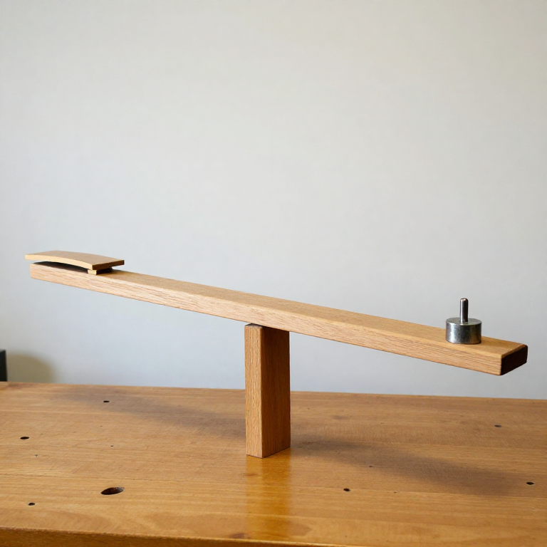


Cayley's Whirling Arm and the Aerofoil
Istruzioni
Separate the three jobs before building anything
Separate the three jobs before building anything
The insight costs nothing and changes everything that follows.
- On paper, list what a flying machine must do: hold itself up, move forward, and stay pointed the right way.
- Sketch a bird’s wingbeat and try to mark which part of the stroke does which job.
- Now sketch a fixed wing, a separate propulsor and a tail, and mark the same three jobs.
In the bird sketch the three jobs are hopelessly entangled; in the second they are three separate components you can design, test and improve independently. That is the whole of Cayley’s advance, and it is a design principle far beyond aviation: when one mechanism is doing three jobs, you cannot improve any of them without disturbing the others.
Cayley engraved this arrangement on a small silver disc in 1799 — a fixed wing, a rower’s paddles for thrust, a cruciform tail. The disc is in the Science Museum in London. It is worth understanding that his machine did not work in 1799; the point is that the LAYOUT was right, and every aircraft since has used it.Materiali per questo passaggio:
 Carta millimetrata1 pad
Strumenti necessari:
 Goniometro
 Squadra combinata
 Calibro digitale da 6 pollici
Build the whirling arm
Build the whirling arm
A rotating beam turns a wind tunnel you cannot afford into one you can build in an afternoon.
- Make a rigid arm about 1 m long from a hardwood or aluminium strip, balanced on a low-friction pivot — a ball bearing pressed into a wooden block works well.
- Fit a counterweight at one end and a mount for the test surface at the other, with the mount free to be set at a measured angle.
- Drive it by a falling weight on a cord wound round the spindle, so the driving force is known and constant.
- Mark the arm so you can count revolutions, and time them.
A falling weight is the key detail: it gives a known, steady input rather than the variable push of a hand. Cayley used exactly this, because the whole point is quantitative comparison. If you drive it by hand you will produce beautiful spinning and no data.
The whirling arm has one flaw its inventors could not escape, and it is worth knowing before you trust your numbers: after the first revolution the test surface is flying through air that its own previous passage has already set moving. The measured lift comes out low. This is precisely the error that later bit Lilienthal, and precisely why the Wrights eventually abandoned whirling arms for a straight-line tunnel.Materiali per questo passaggio:
 Tavoletta di tiglio1 foglio
 Cuscinetto a sfere2 pezzi
 Tubo di ottone da 1/2 pollice di diametro esterno1 pezzo
 Colla da legno1 bottiglia
Strumenti necessari:
 Sega a nastro da banco
 Trapano a colonnaCalibro digitale da 6 polliciSquadra combinata
 Serie di lime
 Morsetto a C
 Occhiali di sicurezza trasparenti
Measure a flat plate at a series of angles
Measure a flat plate at a series of angles
Establish the baseline everyone assumed was the answer.
- Mount a flat plate — thin balsa or card, roughly 100 × 25 mm — on the arm.
- Set it to 0° and release the driving weight; measure the lift with a spring scale on the mount, or by how much counterweight is needed to restore balance.
- Repeat at 2°, 4°, 6°, 10°, 15° and 20°.
- Plot lift against angle.
Lift rises roughly in proportion to angle, then stops rising and collapses. That collapse is the stall — the airflow has stopped following the upper surface and separated into a turbulent wake. Note the angle where it happens; it is one of the most important numbers in aviation, and you have just measured it rather than read it.
Hold a hand out of a moving car window and you can feel this whole curve, including the sudden loss when you tilt too far. The whirling arm just lets you put a number on what your hand already knows.Materiali per questo passaggio:
 Tavoletta di balsa1 foglioCarta millimetrata1 pad
Strumenti necessari:
 Dinamometro a mollaGoniometro
 Goniometro digitaleCalibro digitale da 6 polliciOcchiali di sicurezza trasparenti
Now curve the surface, and find Cayley's result
Now curve the surface, and find Cayley's result
This is the measurement that founded the aerofoil.
- Make a second surface of identical area, but curved — a shallow arc, roughly 1 part depth to 15 parts chord.
- Run the identical series of angles.
- Plot both curves on the same axes.
- Compare the maximum lift, and the angle at which each stalls.
The curved surface produces more lift than the flat plate at every angle, and it goes on working to a higher angle before stalling. There is no obvious reason it should: it has the same area and is made of the same stuff. But a cambered surface turns the airflow more smoothly and keeps it attached longer, and the flow stays attached because it is not asked to negotiate a sharp change of direction at the leading edge.
This single result is why aircraft wings are curved and not flat, and it was found by measurement, not derivation. Cayley did not have a theory of circulation — that arrived a century later with Lanchester and Kutta. He had a spinning stick and a scale, and he was right.
Try a third surface: the same camber but with the high point moved forward, at about a third of the chord rather than the middle. It will usually beat both. You are now doing aerofoil design, and you have the apparatus to keep going.Materiali per questo passaggio:
Tavoletta di balsa1 foglioColla da legno1 bottigliaCarta millimetrata1 padStrumenti necessari:
Dinamometro a mollaGoniometroCalibro digitale da 6 polliciSerie di lime Levigatrice a nastroOcchiali di sicurezza trasparenti
Find where the lift acts, and why it decides the tail
Find where the lift acts, and why it decides the tail
Lift has a magnitude, which you have measured, and a location, which decides whether the machine is controllable.
- Suspend a test wing from a thread and find the point where it balances in still air.
- Now run it on the arm and note whether it wants to pitch nose-up or nose-down at each angle.
- Move the mounting point forward and back until the pitching tendency is minimised, and record where that is along the chord.
The point where lift effectively acts — the centre of pressure — MOVES as the angle changes, and on a cambered surface it moves forward as the angle increases. That is a vicious property: a small nose-up disturbance increases the angle, which moves the lift forward, which pitches the nose up further. The wing is unstable by itself and will diverge.
The tail is the answer, and now you can see why it is not decoration. A surface set well behind the wing at a slightly lower angle produces a restoring moment: pitch up, and the tail’s angle increases, its lift increases, and it pushes the nose back down. Cayley’s cruciform tail was not copying a bird’s feathers — it was a stability device, and he understood it as such.
Reverse-engineering note: this is why the centre of gravity of a model glider must sit ahead of the wing’s centre of pressure, typically at 25 to 33 percent of the chord. Get it wrong by a centimetre and the model either dives or oscillates. Every trimming instruction in every model kit descends from this measurement.Materiali per questo passaggio:
Tavoletta di balsa1 foglio Listelli di balsa1 fascio
 Plastilina da zavorra1 confezione
Strumenti necessari:
Dinamometro a mollaGoniometroCalibro digitale da 6 pollici Bilancia digitaleGoniometro digitaleOcchiali di sicurezza trasparenti
Materiali
8- 1 padSegnaposto
- 1 foglioSegnaposto
- Segnaposto
- Segnaposto
- 1 bottigliaSegnaposto
- 1 foglioSegnaposto
- 1 fascioSegnaposto
- 1 confezioneSegnaposto
Strumenti richiesti
12- Segnaposto
- Segnaposto
- Segnaposto
- Segnaposto
- Segnaposto
- Segnaposto
- Segnaposto
- Segnaposto
- Segnaposto
- Segnaposto
- 1 vendor sell this, none ship to you yetSegnaposto
- Segnaposto
Blueprint correlati
Questi blueprint condividono conoscenze — tecniche, materiali o principi

CC0 Pubblico dominio
Questo progetto è rilasciato sotto CC0. Sei libero di copiare, modificare, distribuire e utilizzare quest'opera per qualsiasi scopo, senza chiedere permesso.
Supporta il Maker acquistando prodotti tramite il suo progetto dove guadagna una Commissione Maker stabilita dai venditori, oppure crea una nuova iterazione di questo progetto e includilo come collegamento nel tuo progetto per condividere i ricavi.