ARTE
BELLEZZA E BENESSERE
MESTIERE
CULTURA E STORIA
DIVERTIMENTO
AMBIENTE
CIBO E BEVANDE
INGEGNERIA INVERSA
SCIENZE
SPORT
TECNOLOGIA
INDOSSABILI
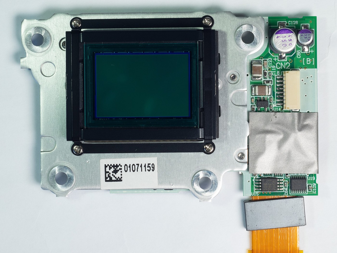


The Charge-Coupled Device
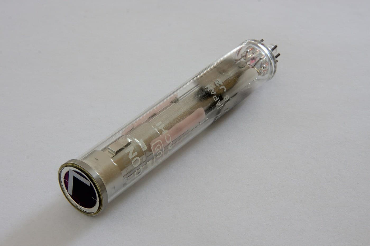
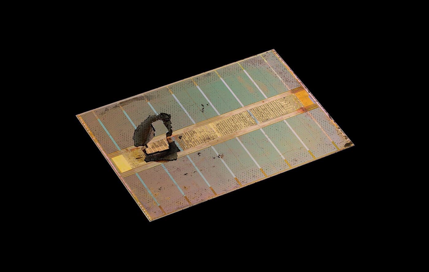
Boyle and Smith, 1969, sketched in an hour on a blackboard; Nobel Prize 2009. A CCD pixel is the DRAM cell read the opposite way: DRAM holds charge and refreshes it in place, a CCD SHIFTS each packet down the row to one amplifier, a bucket brigade for electrons. Because it collects charge on a fixed grid instead of scanning a beam, it kills the vidicon's two diseases — distortion and lag — at a stroke. The price: move charge thousands of times and lose none.
Avanzato
6 hours
Istruzioni
1
1
The pixel is the DRAM cell, read by moving the charge
The pixel is the DRAM cell, read by moving the charge
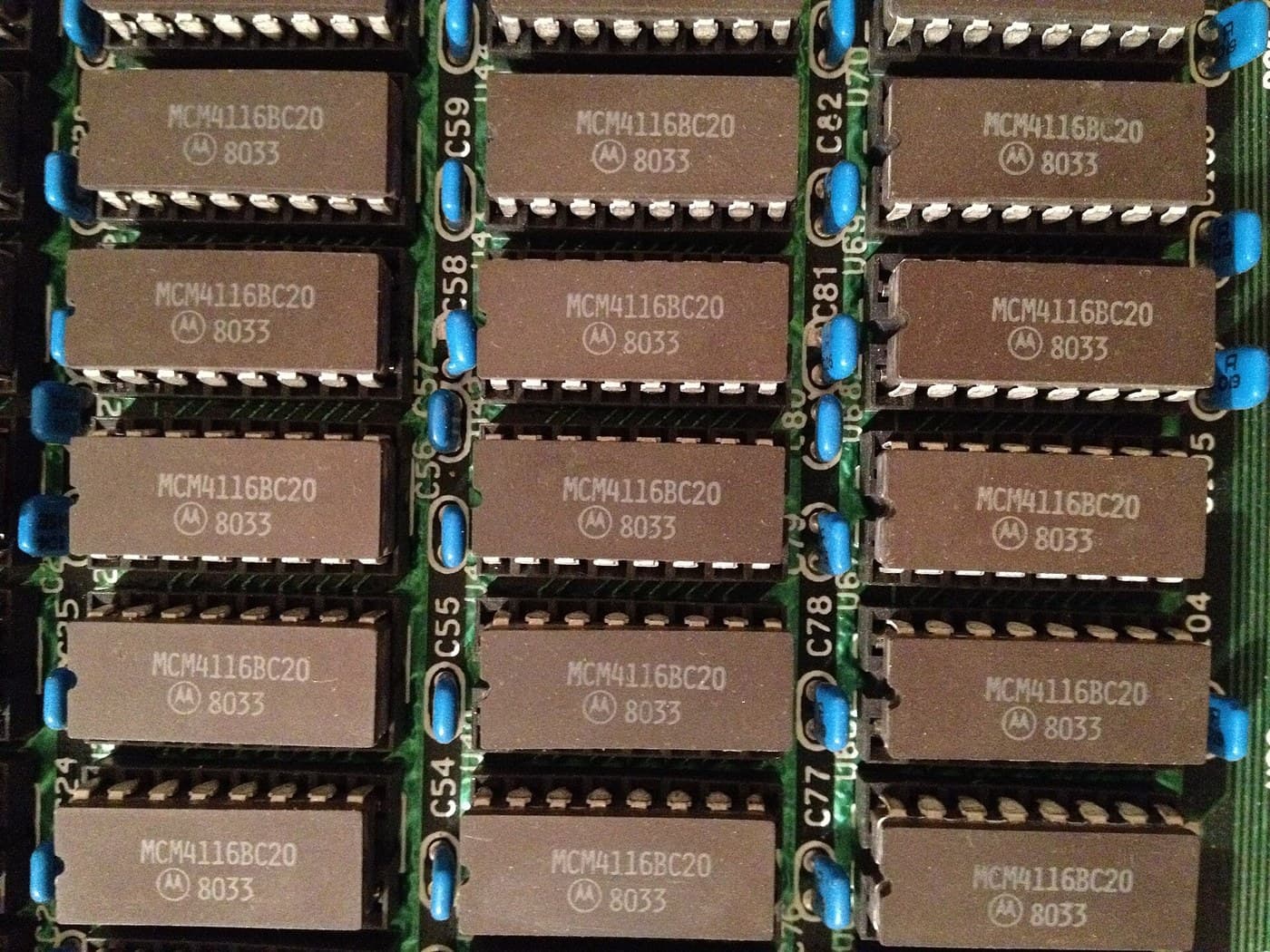
The pixel is the DRAM cell. A gate over silicon makes a potential well; in DRAM you fill it to mean a 1, in a CCD light fills it with electrons. The difference is the whole invention: DRAM reads each cell in place (a wire and an amplifier per column); a CCD MOVES the charge, tipping each packet into the next well like water between buckets, to a single amplifier at the end. Almost no wires, but every packet is transferred thousands of times.
2
2
The bucket brigade: how one image becomes one signal
The bucket brigade: how one image becomes one signal
Follow one photon to the output. Expose (each well fills like a bucket in the rain); clock the whole image DOWN row by row into a readout register; clock that register SIDEWAYS into one amplifier that weighs each packet in turn. One amplifier reads the entire image, so there is no pixel-to-pixel gain variation. The vidicon's distortion (no beam) and lag (wells fully cleared) are simply gone; the new failure modes are transfer loss and dark current.
Flow
Loading...
Strumenti necessari:
 Computer da tavolo
3
3
Why astronomers freeze their sensors: dark current and transfer efficiency
Why astronomers freeze their sensors: dark current and transfer efficiency
Caricamento del notebook Jupyter…
Strumenti necessari:
Computer da tavolo4
4
Measure real dark current against temperature
Measure real dark current against temperature
You cannot clock a bare CCD, but you can measure the physics that rules it — dark current rising exponentially with temperature — on any cheap photodiode. Read a reverse-biased diode's leakage in the dark at several temperatures; the slope of log(current) vs 1/T gives the doubling temperature, ~6-10 C, the same number that forces observatories to pour liquid nitrogen over their cameras.
ccd_darkcurrent.inocpp
Strumenti necessari:
 Scheda di sviluppo ESP32
 Sensore di temperatura DS18B20
 Breadboard
 Fotodiodo (BPW34)
 Kit di resistenze
Strumenti richiesti
6- Segnaposto
- Segnaposto
- Segnaposto
- 1 vendor sell this, none ship to you yetSegnaposto
- Segnaposto
- 2 vendors sell this, none ship to you yetSegnaposto
Blueprint correlati
Questi blueprint condividono conoscenze — tecniche, materiali o principi

CC0 Pubblico dominio
Questo progetto è rilasciato sotto CC0. Sei libero di copiare, modificare, distribuire e utilizzare quest'opera per qualsiasi scopo, senza chiedere permesso.
Supporta il Maker acquistando prodotti tramite il suo progetto dove guadagna una Commissione Maker stabilita dai venditori, oppure crea una nuova iterazione di questo progetto e includilo come collegamento nel tuo progetto per condividere i ricavi.