Collaborazione
ARTE
BELLEZZA E BENESSERE
MESTIERE
CULTURA E STORIA
DIVERTIMENTO
AMBIENTE
CIBO E BEVANDE
INGEGNERIA INVERSA
SCIENZE
SPORT
TECNOLOGIA
INDOSSABILI
Toggle-Lever Churn: A Crank Crooks and Straightens a Jointed Lever, Rocking a Walking Beam Twice Each Turn
Buttercup

Creato da

Buttercup

11. novembre 2026IE
0
0
0
0
0

Toggle-Lever Churn: A Crank Crooks and Straightens a Jointed Lever, Rocking a Walking Beam Twice Each Turn

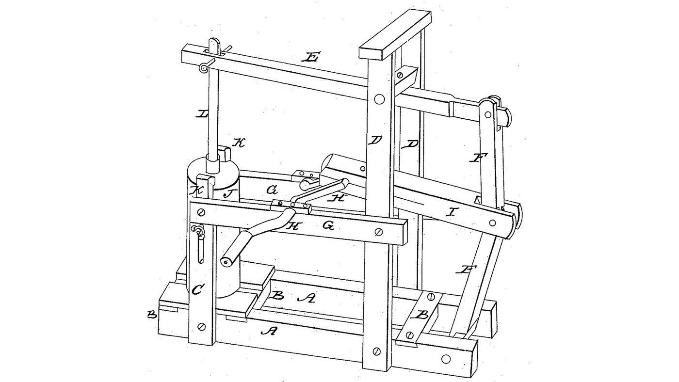
Edwin B. Clement of Barnet, Vermont, received US 27,205, dated 21 February 1860, for a churn. A walking beam on tall posts carries the dasher staff at one end; its other end is joined to a toggle-jointed lever standing on a shaft in the ends of the sills. A crank pushes and pulls the toggle's knee, crooking and straightening it, so the dasher goes "up and down twice to one revolution of the crank". The patent gives no sizes; every size here is ours.
Avanzato
About 3 days, plus printing

Istruzioni

1

Two strokes to one turn

Caricamento del notebook Jupyter…
2

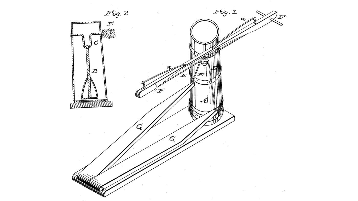
A crank that strokes a dasher, the year before

Austin's crank strokes the dasher once a turn. Clement's toggle gives two strokes a turn.
3

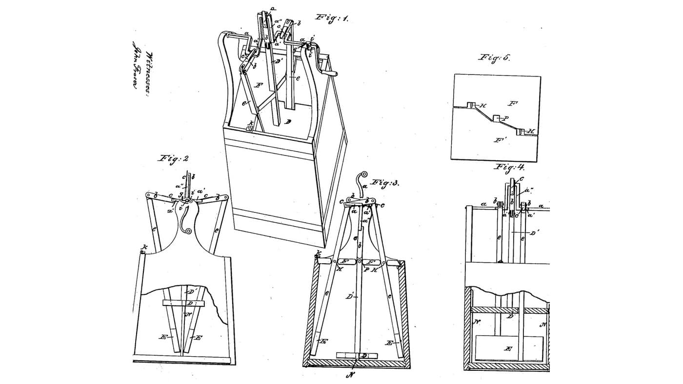
A crank-driven dasher, one week before

Willson turns his dasher's crank with a bow. Clement keeps the hand crank and adds a beam and toggle.
4

Read US 27,205

"One end of the walking beam is connected with a toggle jointed lever, the lower end of which lever is connected with a shaft that turns or rocks in the ends of the sills A, A, see letter F F." ... "I now come to the operation, which is simply to turn the crank H, which will alternately crook and straighten the toggle jointed lever causing the dasher to move up and down twice to one revolution of the crank."
5

Print the dasher

Cone dasher 160 mm across, open underneath, with a socket 22.6 mm across for the dasher staff. PETG, 0.2 mm layers, 40 % infill, 4 walls.
File di designSTLCC0 - Free
6

Frame: sills A, cross ties B, posts C and D

From pine lumber cut two sills 80 x 100 mm, 1250 mm long, and lay them 400 mm apart, centre to centre. Let three cross ties 80 x 30 mm into their tops: one under the churn's place near one end, one in the middle, one 100 mm in from the far end. Screw a board 340 x 300 mm on the end tie, between the sills, for the churn to stand on. Let two posts C, 60 x 60 mm, into the sills either side of the churn's place, reaching 560 mm above the floor, and two posts D 650 mm along from them, reaching 760 mm. Bore the posts D 17 mm across, 650 mm above the floor, for the beam's pivot, and the sills' far ends 21 mm across, 60 mm above the floor and 50 mm from the ends, for the rocking shaft.

Materiali per questo passaggio:

Legname di pinoLegname di pino4 pezzi
Tavola di legno duroTavola di legno duro1 pezzo
Viti da legnoViti da legno40 pezzi
Colla da legnoColla da legno1 pezzo

Strumenti necessari:

Sega circolare da bancoSega circolare da banco
Trapano a batteriaTrapano a batteria
Serie di punte da trapanoSerie di punte da trapano
Set di punte a lanciaSet di punte a lancia
Morsetto a barraMorsetto a barra
Set di cacciavitiSet di cacciaviti
Metro a nastroMetro a nastro
7

Walking beam E and dasher staff L

Cut a hardwood beam 40 x 60 mm, 1010 mm long. Cut a slot 28 x 80 mm through it 30 mm from one end for the staff, and bore 12.8 mm across that slot. Bore 16.8 mm across 650 mm from the slot's centre for a 16 mm stainless pivot through the posts D, and 12.8 mm across 300 mm beyond the pivot for the toggle's pin. Glue a 22 mm hardwood staff into the dasher's socket so its top is 459 mm above the dasher's underside, and bore it 12.8 mm across 414 mm up from the underside; pin it in the beam's slot with a 12 mm stainless pin and split pins.

Materiali per questo passaggio:

Tavola di legno duroTavola di legno duro1 pezzo
Tasselli di legno duroTasselli di legno duro1 pezzo
Colla da legnoColla da legno1 pezzo
Barra di acciaio inossidabileBarra di acciaio inossidabile1 pezzo
Shaft CollarShaft Collar2 pezzi
CoppigliaCoppiglia2 pezzi
Filamento PETGFilamento PETG1 pezzo

Strumenti necessari:

Stampante 3D a filamento (FDM)Stampante 3D a filamento (FDM)
Sega circolare da bancoSega circolare da banco
Seghetto alternativoSeghetto alternativo
Trapano a batteriaTrapano a batteria
Serie di punte da trapanoSerie di punte da trapano
Seghetto per metalliSeghetto per metalli
Lime (lima a mano)Lime (lima a mano)
Carta abrasivaCarta abrasiva
8

Toggle-jointed lever F and rocking shaft

Pass a 20 mm stainless rod through the sills' far ends as the rocking shaft. Cut four hardwood links 15 x 40 mm, each with two 12.8 mm holes 320 mm apart: a pair of lower links on the rocking shaft, and a pair of upper links on the beam's end pin, either side of the beam. Join the four at the knee with one 12 mm stainless pin, the upper pair inside the lower pair, leaving the middle free for the connecting shaft. Secure every pin with split pins.

Materiali per questo passaggio:

Barra di acciaio inossidabileBarra di acciaio inossidabile1 pezzo
Tavola di legno duroTavola di legno duro1 pezzo
Shaft CollarShaft Collar2 pezzi
CoppigliaCoppiglia6 pezzi

Strumenti necessari:

Sega circolare da bancoSega circolare da banco
Trapano a batteriaTrapano a batteria
Serie di punte da trapanoSerie di punte da trapano
Seghetto per metalliSeghetto per metalli
Lime (lima a mano)Lime (lima a mano)
Morsa da bancoMorsa da banco
Carta abrasivaCarta abrasiva
9

Bars G, crank H and connecting shaft I

Screw a hardwood bar G 25 x 60 mm along the outside of each side, from post C to post D, 400 mm above the floor, and bore both 20.8 mm across 378 mm from the posts C. Cut a 20 mm stainless crank shaft 610 mm long, through both bars and 85 mm beyond one. Build the crank in the middle: two hardwood webs 30 x 14 mm, glued and pinned to the shaft with a 32 mm gap, carrying a 12 mm stainless crank pin 150 mm out; cut the shaft away between them. Outside the bar fit a hardwood arm 130 mm long with a dowel handle. Cut a hardwood connecting shaft I 30 x 40 mm with 12.8 mm holes 600 mm apart, from the crank pin to the knee pin. Fit collars either side of the bars.

Materiali per questo passaggio:

Tavola di legno duroTavola di legno duro2 pezzi
Barra di acciaio inossidabileBarra di acciaio inossidabile1 pezzo
Tasselli di legno duroTasselli di legno duro1 pezzo
Colla da legnoColla da legno1 pezzo
Viti da legnoViti da legno8 pezzi
Shaft CollarShaft Collar2 pezzi
CoppigliaCoppiglia2 pezzi

Strumenti necessari:

Sega circolare da bancoSega circolare da banco
Trapano a batteriaTrapano a batteria
Serie di punte da trapanoSerie di punte da trapano
Set di punte a lanciaSet di punte a lancia
Seghetto per metalliSeghetto per metalli
Lime (lima a mano)Lime (lima a mano)
Morsa da bancoMorsa da banco
Morsetto a barraMorsetto a barra
Set di cacciavitiSet di cacciaviti
10

Churn J and hooks K

Bore a 48 mm hole in the centre of the bucket's lid for the staff. Bend two hooks from mild steel flat bar to reach from the posts C over the bucket's rim, and fasten each to its post with a carriage bolt and wing nut, as the patent's hooks are "provided each with a bolt and nut and fastened to the posts C".

Materiali per questo passaggio:

Secchio da 20 litriSecchio da 20 litri1 pezzo
Piatto di acciaio dolcePiatto di acciaio dolce1 pezzo
Bullone a testa tonda e collo quadroBullone a testa tonda e collo quadro2 pezzi
Dado ad aletteDado ad alette2 pezzi

Strumenti necessari:

Trapano a batteriaTrapano a batteria
Serie di punte da trapanoSerie di punte da trapano
Set di punte a lanciaSet di punte a lancia
Seghetto per metalliSeghetto per metalli
Morsa da bancoMorsa da banco
Lime (lima a mano)Lime (lima a mano)
Chiave regolabile a rullinoChiave regolabile a rullino
11

The build in 3D

FreeCAD model of this build, the churn cut through the middle: the sills, ties and posts, the walking beam on the posts D, the dasher staff, the toggle-jointed lever on the rocking shaft, the crank in the bars G and the connecting shaft to the toggle's knee.
File di designBLENDCC0 - Free
12

Churn

Lift the beam's dasher end, stand the bucket on its board with about 10 litres of heavy cream at about 15 °C, checked with the thermometer, lower the dasher in, put on the lid over the staff and fasten the hooks. Turn the crank steadily, timing it. When the butter comes, unhook the bucket, lift the dasher out, pour off the buttermilk into a bowl, wash the butter in cold water until it runs clear, salt and weigh it.

Materiali per questo passaggio:

Panna da montarePanna da montare10 l
Sale marino grossoSale marino grosso1 pezzo
AcquaAcqua1 pezzo

Strumenti necessari:

Termometro a sonda permanenteTermometro a sonda permanente
CronometroCronometro
Bilancia digitale da cucinaBilancia digitale da cucina
Grande ciotola da impasto in acciaio inossidabileGrande ciotola da impasto in acciaio inossidabile
13

Troubleshooting

Toggle-lever churn troubleshooting.

Flow

Loading...
14

History and honest limits

**Edwin B. Clement** of Barnet, Caledonia County, Vermont, US 27,205, 21 February 1860, "Churn". He claimed "the arrangement of the toggle joint F, walking beam E, crank H, and connecting shaft I". The patent gives no sizes and does not show one post C; every size here is ours, as are the bucket, the cone dasher, the paired links and the built-up crank.

Materiali

16

Strumenti richiesti

18

File di progetto

2

CC0 Pubblico dominio

Questo progetto è rilasciato sotto CC0. Sei libero di copiare, modificare, distribuire e utilizzare quest'opera per qualsiasi scopo, senza chiedere permesso.

Supporta il Maker acquistando prodotti tramite il suo progetto dove guadagna una Commissione Maker stabilita dai venditori, oppure crea una nuova iterazione di questo progetto e includilo come collegamento nel tuo progetto per condividere i ricavi.

Commenti

(0)

Accedi per partecipare alla discussione

Caricamento commenti...