Collaborazione
ARTE
BELLEZZA E BENESSERE
MESTIERE
CULTURA E STORIA
DIVERTIMENTO
AMBIENTE
CIBO E BEVANDE
INGEGNERIA INVERSA
SCIENZE
SPORT
TECNOLOGIA
INDOSSABILI
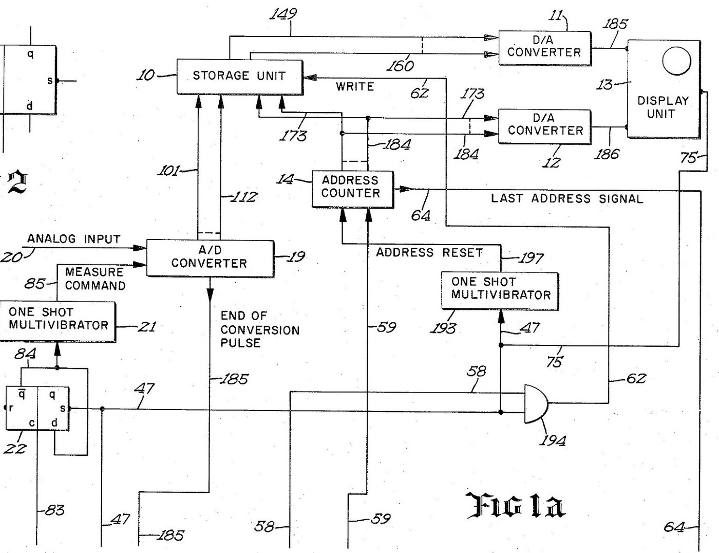


Digital Oscilloscope: Waveform Stored in Memory and Shown on a CRT (Schumann, Nicolet, US 3,816,815, 1974)
An oscilloscope with a memory. After a trigger, an analog-to-digital converter measures the input at regular intervals and writes each reading into its own memory register, replacing the old one. The screen then shows the memory: each register's number sets the beam's height, its address sets the beam's place across. The last waveform can be held on the screen as long as you like.
Result: a digital storage oscilloscope with 4,096 points of 12 bits, refresh and hold modes and single-shot capture.
Source: R. W. Schumann (Nicolet), US 3,816,815 (1974). Unknown: sample rate, bandwidth, voltages and the parts used. Picture: the patent drawing.
Esperto
Unknown
Istruzioni
1
1
Sample and convert the input
Sample and convert the input
Bring the analog input to an analog-to-digital converter, through a BNC socket. A sampling oscillator, divided by four by two flip-flops so the first reading comes soon after the sweep starts, fires a one-shot multivibrator that gives the converter its measure command. The converter holds each 12-bit result on its output lines and signals the end of each conversion. Ours: a BNC socket. Not given: the sample rate.
Materiali per questo passaggio:
 Convertitore analogico-digitale1 12-bit converter
 Oscillatore di clock1 sampling oscillator
 Assortimento di circuiti integrati logici1 flip-flops, one-shots, gates
 Set di connettori coassiali (BNC / SO-239)1 input socket
Strumenti necessari:
 Saldatore a stagno
 Spelafili
2
2
Store each reading in memory
Store each reading in memory
Wire an integrated-circuit memory of 4,096 registers, 12 bits each, that can be read without changing it. A 12-bit address counter picks the register. On each write command the register at the current address takes the last reading from the converter, and the counter steps on. When the sweep starts, a one-shot resets the counter to zero. When it reaches the last address, its last-address signal ends the sweep.
Materiali per questo passaggio:
 Memoria a circuiti integrati1 4,096 x 12-bit store
Strumenti necessari:
Saldatore a stagnoSpelafili3
3
Drive the CRT from the memory
Drive the CRT from the memory
Feed the addressed register's number to one digital-to-analog converter and the address to a second. Their outputs drive the vertical and horizontal deflection plates of a cathode-ray tube, so the beam always stands at the height of the stored reading and at the place of its address. Wire the sweep line to the tube's intensifier, to brighten the trace while a waveform is being taken.
Materiali per questo passaggio:
 Convertitore digitale-analogico2 vertical and horizontal
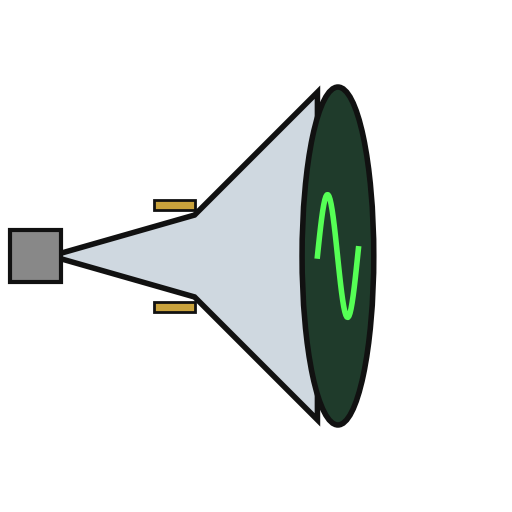 Tubo a raggi catodici1 display tube
Strumenti necessari:
Saldatore a stagnoSpelafili4
4
Wire the trigger and the modes
Wire the trigger and the modes
A trigger input, usually from the leading edge of the input waveform, starts the sweep, once a measure flip-flop has armed it. Put a two-position mode switch on the face: MODE I and MODE II. Add a push button in the probe, a switch on the panel and an external initiate input; each goes through a flip-flop that removes contact bounce. Two more oscillators step the memory round to refresh the display between waveforms. Mount it all in a case with its supply. Ours: toggle switches, an aluminium case, a DC supply. Not given: the supply voltages.
Materiali per questo passaggio:
Oscillatore di clock2 display sequencing oscillators Interruttore a levetta2 mode and panel switches
 Pulsante1 probe switch
 Contenitore in alluminio1 case
Strumenti necessari:
 Alimentatore in corrente continua
 Trapano a colonnaSaldatore a stagno
5
5
Capture and hold a waveform
Capture and hold a waveform
In MODE I, refresh: each new triggered waveform replaces the last on the screen. Press the probe or panel switch to hold: new waveforms are rejected and the last one stays on the screen. In MODE II the screen normally holds; on command, it takes the first waveform after the command, stores it and shows it steadily. Test it with a known signal.
Strumenti necessari:
 Generatore di funzioni
Materiali
10- 1 12-bit converterSegnaposto
- 2 display sequencing oscillatorsSegnaposto
- 1 flip-flops, one-shots, gatesSegnaposto
- 1 input socketSegnaposto
- 1 4,096 x 12-bit storeSegnaposto
- 2 vertical and horizontalSegnaposto
- 1 display tubeSegnaposto
- Segnaposto
- Segnaposto
- 1 caseSegnaposto
Questo progetto realizza

Blueprint correlati
Questi blueprint condividono conoscenze — tecniche, materiali o principi
CC0 Pubblico dominio
Questo progetto è rilasciato sotto CC0. Sei libero di copiare, modificare, distribuire e utilizzare quest'opera per qualsiasi scopo, senza chiedere permesso.
Supporta il Maker acquistando prodotti tramite il suo progetto dove guadagna una Commissione Maker stabilita dai venditori, oppure crea una nuova iterazione di questo progetto e includilo come collegamento nel tuo progetto per condividere i ricavi.