ARTE
BELLEZZA E BENESSERE
MESTIERE
CULTURA E STORIA
DIVERTIMENTO
AMBIENTE
CIBO E BEVANDE
INGEGNERIA INVERSA
SCIENZE
SPORT
TECNOLOGIA
INDOSSABILI
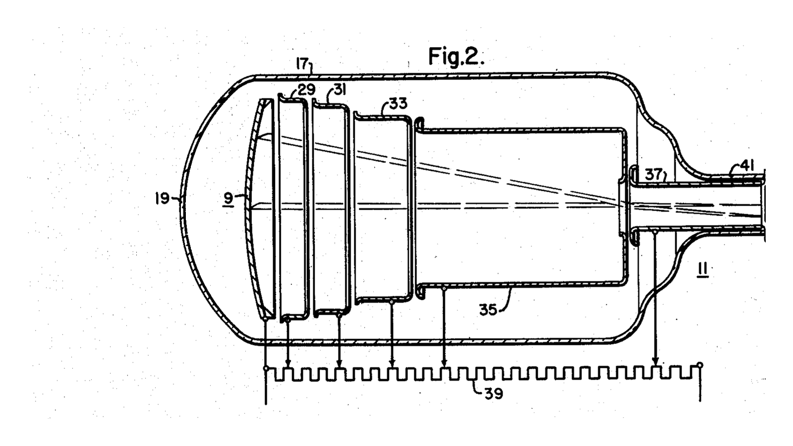


Mason & Coltman Image Intensifier
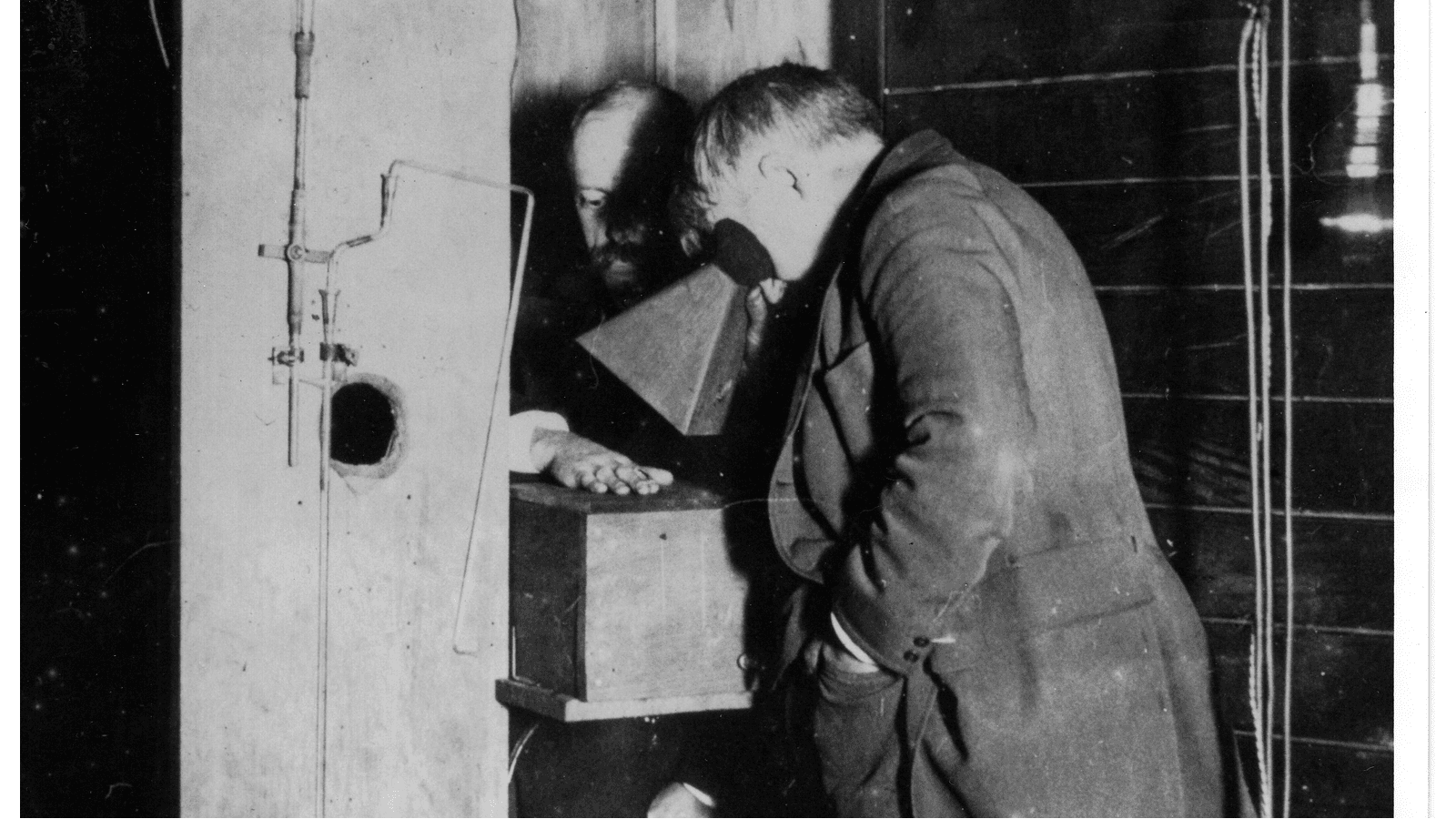
For fifty years, watching an X-ray image live meant sitting in a completely dark room. The fluoroscopic screen from the first blueprint in this batch is genuinely faint - so faint that radiologists wore red goggles for twenty minutes beforehand so their eyes would already be dark-adapted when they walked in. They were reading a barely-glowing screen with the rod cells of the eye, which have no colour vision and poor acuity, while standing next to an unshielded beam.
**US 2,523,132**, "Photosensitive apparatus", Ruric C. Mason and John W. Coltman, assigned to Westinghouse, filed 10. August 1949 and granted 19. September 1950. It made the image thousands of times brighter, and it did it with two multiplied tricks.
**Minification.** Take the light from a large input screen and land it on a small output screen. The same total light in a fraction of the area is brighter by the ratio of the areas - a 230 mm input onto a 25 mm output is roughly 85 times, from geometry alone, costing nothing.
**Flux gain.** The input screen's light releases electrons from a photocathode; those electrons are accelerated through tens of kilovolts and slam into the output phosphor carrying far more energy than the photon that started them, making many light photons each. Another fifty times or so.
Multiply them and the image is thousands of times brighter than the screen it replaced. The doctor could stand in a lit room, look through an eyepiece, and - crucially - point a television camera at it.
**The patent's actual claim is about noise**, which is worth noticing. Its first claim specifies "an X-ray responsive fluorescent screen of the zinc sulphide type" AND "a photoelectric surface which responds substantially only to light in the blue, ultra-violet and higher frequencies". A photocathode sensitive to red light also emits electrons from sheer heat, which arrive as a snowstorm on the output. Matching the photocathode's threshold to the phosphor's blue emission keeps the signal and starves the noise.
**You will build the minification half and measure it**, with a lens instead of electron optics - and then you will measure the thing the whole device cannot do, which is more interesting than the thing it can.
Principiante
90 minutes
Istruzioni
1
1
Make a large, dim, evenly-lit input
Make a large, dim, evenly-lit input
You need a stand-in for a fluoroscopic screen: large, uniform, and genuinely faint.
Take the phosphor screen from the first blueprint in this batch, or a sheet of white acrylic lit from behind through several layers of tracing paper. Aim for something around 150 mm across that you can only just see in a dark room - if it is comfortable to look at, dim it further, because the entire point is a source too faint to work with.
Measure its luminance with a light meter held close, and note the reading and the distance. Then measure the LIT diameter with a ruler - not the diameter of the sheet, the diameter of the part that is actually glowing. That distinction is the first branch of the troubleshooting step and it catches most people.
Put a resolution target on it - a printed set of bars, or a comb of card - so you have something whose sharpness you can judge as well as its brightness.
Materiali per questo passaggio:
 Lastra di acrilico1 pezzo
 Carta vellum (traslucida)3 fogli
Strumenti necessari:
 Esposimetro (luce incidente/riflessa)
 Righello
 Torcia LED da ispezione
 Pellicola trasparente per stampa a getto d'inchiostro
2
2
Minify it, and measure the gain
Minify it, and measure the gain
Use a lens to form a small image of the whole lit screen on a piece of white card. A 50 mm camera lens or a simple magnifier both work; you want an image about 25 mm across, so a reduction of roughly six to one in diameter.
Focus carefully, then measure the image diameter with a caliper and its luminance with the meter at the SAME distance and angle you used in step 1.
Compute the ratio of areas from the two diameters, and compare it with the ratio of the two meter readings. They should be in the same ballpark, and where they differ the flow step tells you why - almost always because the lens aperture is collecting only part of the light cone, or because you measured the sheet rather than the lit patch.
**This is a real intensifier's minification gain, complete.** In the patent's tube the reduction is done by electron optics rather than glass, but the arithmetic is identical, and it is the larger of the two gains in most tubes.
Materiali per questo passaggio:
 Lente convessa1 pezzo
 Fogli di cartone ondulato1 foglio
Strumenti necessari:
Esposimetro (luce incidente/riflessa) Calibro digitale da 6 pollici
 Treppiede (fibra di carbonio, testa a sfera)Righello
3
3
The half you cannot build, and what it is worth
The half you cannot build, and what it is worth
The second gain needs a photocathode, a vacuum and thirty kilovolts, and this blueprint is not going to have you build that. But you can measure its electronic equivalent and see exactly what it does and does not achieve.
Point a photodiode at your minified image and amplify its output with an op-amp at a known gain - ten, then a hundred, then a thousand. Watch the signal on an oscilloscope at each.
The trace gets bigger. Look closely at the fuzz ON the trace: it gets bigger by exactly the same factor. The ratio of signal to noise is identical at every gain setting, because you amplified both together.
That is precisely what the acceleration stage in a real intensifier does. Every photoelectron becomes many output photons, so everything gets brighter - the signal and the statistical fluctuation alike. It is a magnificent brightness amplifier and it is not, and cannot be, an information amplifier.
Materiali per questo passaggio:
 Circuito integrato amplificatore operazionale1 pezzo
 Kit di resistenze1 pezzo
 Breadboard1 pezzo
Strumenti necessari:
 Oscilloscopio
 Multimetro digitale da laboratorio
 Alimentatore da banco regolabile
 Cavetti di prova con pinze a coccodrillo
 Fotodiodo (BPW34)
4
4
The quantum sink, measured with a camera
The quantum sink, measured with a camera
Here is the measurement that explains why the intensifier mattered - and it is not the brightness one.
Photograph your dim screen twice: once at low ISO with a long exposure, once at very high ISO with a short exposure, matched so both images have the same brightness on screen. The high-ISO frame collected far fewer photons and made up the difference with gain.
Now zoom into a flat, evenly-lit area of each and compare the graininess. Better still, measure it: sample a patch and compute the standard deviation of pixel values divided by the mean. The low-ISO frame will be smooth; the high-ISO frame will be visibly speckled, at the same average brightness.
**Gain moved the brightness. It did nothing for the noise, because the noise was set by how many photons were counted.** Signal-to-noise goes as the square root of the number of quanta, so the narrowest point in the chain - the fewest quanta anywhere along it - decides the quality of everything after it. In a real intensifier that point is the X-ray photons absorbed by the input screen, and it is called the quantum sink.
So the prize is not the bright picture. It is that the eye no longer needs a bright picture, which means the tube can be run at a LOWER dose and the amplifier can make up the difference. The image intensifier is a dose-reduction device wearing the costume of a brightness device.
Strumenti necessari:
 Fotocamera digitaleTreppiede (fibra di carbonio, testa a sfera)
 Computer da tavolo
5
5
Two gains, and the one that is not a gain
Two gains, and the one that is not a gain
Caricamento del notebook Jupyter…
6
6
When the gain does not add up
When the gain does not add up
Three measurement faults, then the check that matters more than any of them.
Flow
Loading...
Strumenti necessari:
Esposimetro (luce incidente/riflessa)7
7
Compendium: the TV chain, and what killed the tube
Compendium: the TV chain, and what killed the tube
**What it unlocked immediately.** Once the image was bright enough to photograph, it could be recorded on cine film - cineangiography, which made cardiac catheterisation possible - and then pointed at a television camera, which put the image on a monitor in a lit room, let several people watch at once, and let the radiologist stand somewhere other than in the beam. Almost every safety and workflow improvement in fluoroscopy for thirty years came from that one change in brightness.
**Vignetting, pincushion, and the S-distortion.** Electron optics are not as good as glass. The image is dimmer at the edges than the centre, straight lines bow outward, and the Earth's own magnetic field bends the electron paths enough that rotating the tube changes the distortion - so an intensifier's image warps slightly as the C-arm is swung. Every one of those is a consequence of steering electrons across a large evacuated volume, and none of them exists in a flat panel.
**Caesium iodide, which came from the first blueprint in this batch.** Early tubes used a zinc sulphide input screen, exactly as the patent's claim says. Replacing it with CsI grown in parallel needles roughly doubled the absorbed X-ray fraction while keeping the image sharp - which, per the quantum sink, is a real information gain rather than a brightness one. It is the single biggest improvement the technology ever received.
**What replaced it.** The flat panel detector: a scintillator laid directly onto a matrix of photodiodes with a thin-film transistor behind each. No vacuum, no electron optics, no distortion, no vignetting, and a device 30 mm thick instead of half a metre. Image intensifiers are still in service and still being made for mobile C-arms where cost matters, but the direction is one way.
**And the honest summary of the whole thing:** the intensifier did not make the picture better. It made a picture of the same quality visible under conditions where a human could use it - and then let the dose come down until the picture was as poor as clinicians would tolerate. That is a very common shape in engineering, and it is worth recognising it for what it is.
Materiali
7- 1 pezzoSegnaposto
- 3 fogliSegnaposto
- 1 pezzoSegnaposto
- 1 foglioSegnaposto
- Segnaposto
- Segnaposto
- Segnaposto
Strumenti richiesti
13- Segnaposto
- Segnaposto
- Segnaposto
- Segnaposto
- Segnaposto
- Segnaposto
- Segnaposto
- Segnaposto
- Segnaposto
- Segnaposto
- Segnaposto
Blueprint correlati
Questi blueprint condividono conoscenze — tecniche, materiali o principi


CC0 Pubblico dominio
Questo progetto è rilasciato sotto CC0. Sei libero di copiare, modificare, distribuire e utilizzare quest'opera per qualsiasi scopo, senza chiedere permesso.
Supporta il Maker acquistando prodotti tramite il suo progetto dove guadagna una Commissione Maker stabilita dai venditori, oppure crea una nuova iterazione di questo progetto e includilo come collegamento nel tuo progetto per condividere i ricavi.