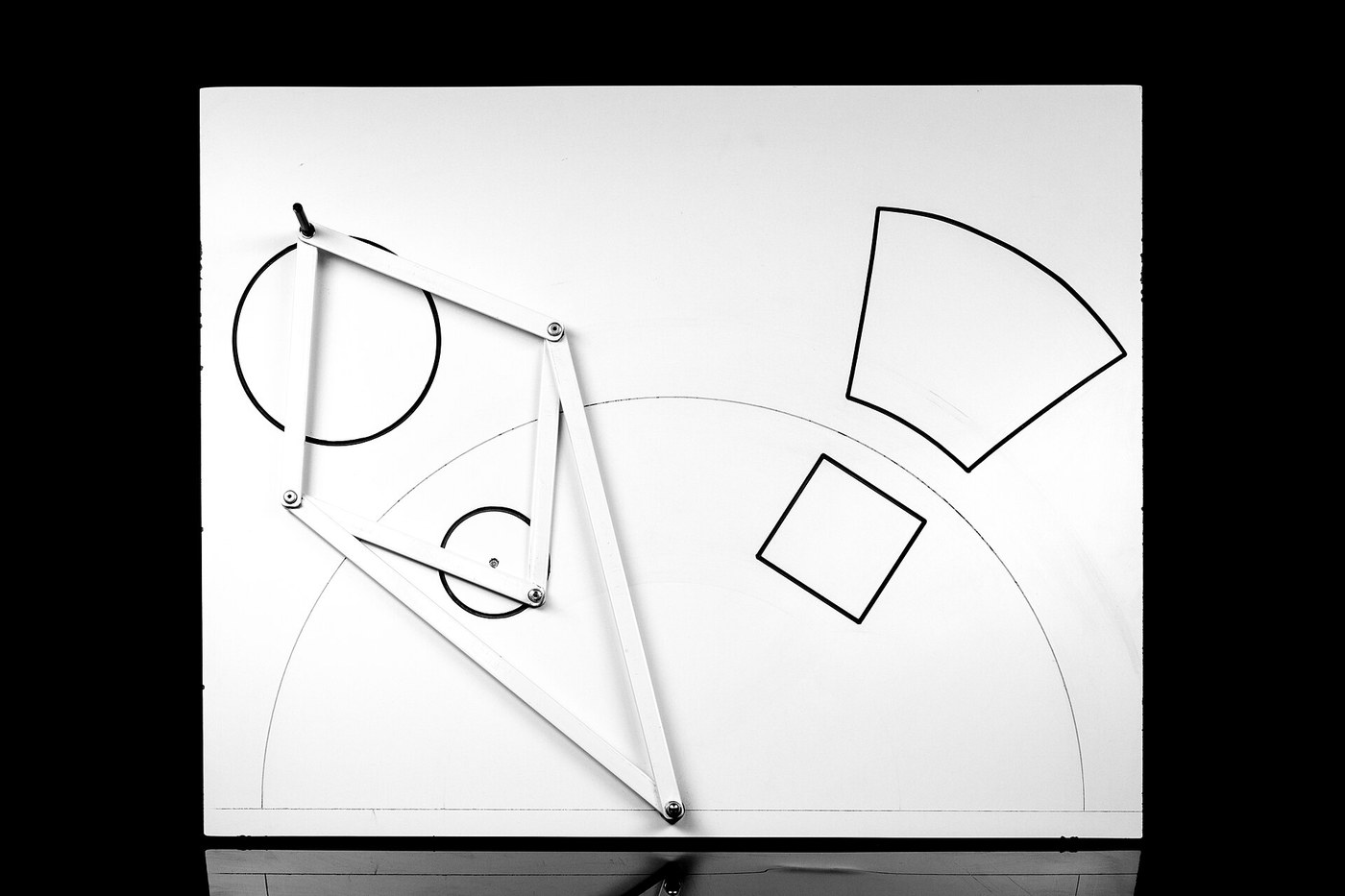


Peaucellier-Lipkin Linkage
Istruzioni
Cut seven bars to length, accurately
Cut seven bars to length, accurately
This mechanism is exact only if the bars are. Length error translates directly into line error.
- From 3 mm aluminium flat bar, cut four rhombus links at 60 mm hole centres and two anchor links at 100 mm hole centres.
- Cut one base link to carry the two fixed pivots, 40 mm between centres.
- Mark and centre-punch every hole centre using the caliper, not a rule.
- Drill all pivot holes 4.1 mm.
- File the ends round so no corner can foul a neighbouring bar through the full sweep.
Modern build spec (derived). 4.1 mm holes on M4 pivots give a close running fit without a reamer. The original was made in steel bar with turned pins in bushes; aluminium and a slightly oversize hole gets a maker to a working mechanism in an evening.
Clamp pairs of identical bars together and drill them as a stack. Four rhombus links drilled separately will differ by a few tenths, and the mechanism will trace a line with a visible kink at mid-travel.Materiali per questo passaggio:
 Piatto di alluminio1 pezzo
Strumenti necessari:
 Archetto per seghetto con lame
 Morsa da banco
 Bulino da centro
 Trapano a batteria
 Serie di punte da trapano
 Calibro digitale da 6 pollici
 Serie di lime
Assemble the rhombus
Assemble the rhombus
Four equal bars forming a diamond that can flex but not change its side lengths.
- Join the four 60 mm links into a rhombus at four pivots.
- At each pivot use an M4 × 16 socket head cap screw, an M4 flat washer either side of the joint, and an M4 nylon insert lock nut.
- Tighten each until the joint swings freely under its own weight but has no side rock.
Why a washer between every pair of bars: aluminium on aluminium picks up and stiffens as it wears. A washer separates the faces, spreads the clamp load and keeps the pivot free after hundreds of cycles.
The nylon lock nut is doing something specific here — it lets you set a precise running clearance and keeps it. Tighten a plain nut to the same feel and the joint will either seize as it settles or shake loose.Materiali per questo passaggio:
 Vite a testa cilindrica con esagono incassato4 pezzi
 Rondella piana12 pezzi
 Dado autobloccante con inserto in nylon4 pezzi
Strumenti necessari:
 Serie di chiavi a brugola
Add the anchor arms and the driving crank
Add the anchor arms and the driving crank
The two long arms are what make the inversion work.
- Pivot both 100 mm anchor links to a single fixed point O on the baseplate.
- Connect their far ends to the two OPPOSITE corners of the rhombus — the corners that lie on the line through O.
- Fix a driving crank of length equal to half the distance from O to the fixed crank centre.
- Pivot the crank's free end to the near rhombus corner, point P.
The geometric condition that matters: the crank pivot must sit so that P travels on a circle THROUGH the point O. That is the whole trick — inverting a circle that passes through the centre of inversion is what yields a straight line. Set the crank centre anywhere else and the output traces an arc.
Measure the distance from O to the crank centre and make the crank exactly half of it. This single dimension is the difference between a mechanism that draws a line and one that draws a curve.Materiali per questo passaggio:
Vite a testa cilindrica con esagono incassato4 pezziRondella piana12 pezziDado autobloccante con inserto in nylon4 pezzi Pannello di compensato1 foglio
Strumenti necessari:
Serie di chiavi a brugolaTrapano a batteriaCalibro digitale da 6 pollici Squadra combinata
Draw the line and measure the error
Draw the line and measure the error
Do not take the claim on trust — measure it.
- Fit a pencil or a fine marker at the output corner Q.
- Sweep the crank through its full arc, letting the pencil draw.
- Lay a steel straight edge against the drawn line.
- Measure the largest gap anywhere along it with a feeler or by eye against a lamp.
Materiali per questo passaggio:
Pannello di compensato1 confezioneStrumenti necessari:
Calibro digitale da 6 polliciSquadra combinataHistory and why it mattered
History and why it mattered
Charles-Nicolas Peaucellier, a French army engineer, published the linkage in 1864. Yom Tov Lipman Lipkin, a Lithuanian mathematician, discovered it independently a few years later, and both names are attached. James Joseph Sylvester lectured on it in London in 1874 and reported that a colleague, on being shown a model, declared it had "a beautiful motion" and would not give it back.
The problem it closed. Converting rotation into straight-line motion was one of the practical obsessions of the steam age, because a piston rod must move straight while a crank goes round. James Watt's own linkage of 1784 was an approximation, and he wrote that he was prouder of it than of anything else he had invented — an approximation good over a short arc was worth that much. Peaucellier proved the exact solution existed.
Why it did not sweep the field. Eight bars and seven pivots is a great deal of mechanism, and every pivot contributes clearance, friction and a wear point. The whole assembly must be built precisely or the exactness is lost in slop — which the measurement in step 4 demonstrates directly. By the time it was published, machine tools could produce accurate flat slides cheaply, and a crosshead sliding in a guide solved the same problem with two parts instead of eight.
Its siblings in this catalogue reach the same goal differently: Watt's linkage uses three bars and accepts a slight figure-of-eight deviation; Chebyshev's uses four and optimises the approximation mathematically. Peaucellier's is exact and expensive. Which is right depends entirely on how straight is straight enough and how many pivots you can afford to make well — the trade-off is the lesson, not the winner.
Materiali
5- 1 pezzoSegnaposto
- Segnaposto
- 12 pezziSegnaposto
- Segnaposto
- 1 confezioneSegnaposto
Strumenti richiesti
9- Segnaposto
- Segnaposto
- Segnaposto
- 1 vendor sell this, none ship to you yetSegnaposto
- Segnaposto
- Segnaposto
- Segnaposto
- Segnaposto
- Segnaposto
Blueprint correlati
Questi blueprint condividono conoscenze — tecniche, materiali o principi


CC0 Pubblico dominio
Questo progetto è rilasciato sotto CC0. Sei libero di copiare, modificare, distribuire e utilizzare quest'opera per qualsiasi scopo, senza chiedere permesso.
Supporta il Maker acquistando prodotti tramite il suo progetto dove guadagna una Commissione Maker stabilita dai venditori, oppure crea una nuova iterazione di questo progetto e includilo come collegamento nel tuo progetto per condividere i ricavi.