

Constant-Velocity Joint
To drive the front wheels of a car you must send power down a shaft that also has to bend — because the front wheels steer, and they bounce up and down on the suspension. The old answer, the Cardan or Hooke joint, bends fine but has a hidden vice: at an angle it speeds the output shaft up and slows it down twice per revolution. On a driven, steered wheel that shudder is unbearable.
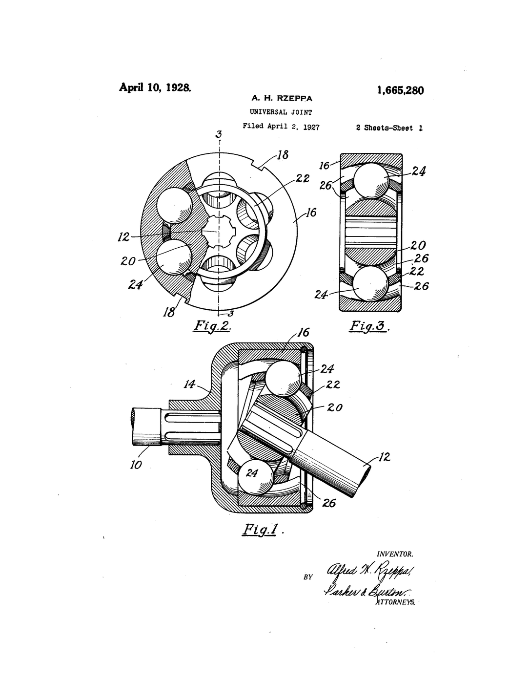
Rzeppa's joint bends AND keeps the speed dead constant. Steel balls run in curved grooves between an inner and an outer race, held by a cage. However the joint is angled, the geometry forces every ball to sit in the exact plane that bisects the angle between the two shafts — and a ball in that bisecting plane transmits rotation with no speed fluctuation at all.
Constant velocity in, constant velocity out, at any steering angle — which is what finally made front-wheel drive smooth enough to sell.
US Patent 1,665,280, "Universal Joint", granted 10 April 1928 (filed 2 April 1927) to Alfred H. Rzeppa of Detroit, Michigan.
Istruzioni
Read the claim and the real goal
Read the claim and the real goal
Rzeppa's patent is titled "Universal Joint", but its aim is a joint that transmits constant velocity through an angle. Note the goal — it is what the Cardan joint fails to do.
Build a Hooke (Cardan) joint first
Build a Hooke (Cardan) joint first
Make a simple cross-and-yoke universal joint from dowel and a cross pin — two forks joined by a central cross. This is the joint Rzeppa set out to beat.
Materiali per questo passaggio:
 Tondino di legno (spina)1 pezzo
 Tondo di acciaio dolce1 pezzo
Strumenti necessari:
 Pinza universale
Run it straight and mark input against output
Run it straight and mark input against output
With the shafts in a straight line, put a protractor dial on each end. Turn the input in steps and read the output. Straight, they track exactly.
Strumenti necessari:
 Goniometro / misuratore d'angoli
Now bend the joint to 30° and repeat
Now bend the joint to 30° and repeat
Angle the shafts and turn the input in equal steps again. The output runs ahead, then falls behind, twice per turn. Record the biggest lead and lag.
Plot the Hooke joint's speed error
Plot the Hooke joint's speed error
Graph output angle against input angle. It is a wavy line, not straight — the twice-per-rev speed fluctuation that shakes a driven wheel. Steeper angle, bigger wobble.
See the fix in one sentence
See the fix in one sentence
The cure is known: keep the point that carries the drive in the plane that bisects the angle between the shafts. The rest of the build makes balls do exactly that.
Carve an inner race with curved grooves
Carve an inner race with curved grooves
Shape a ball-shaped inner race with curved grooves running along it, one per ball. The groove curvature is what will steer the balls.
Materiali per questo passaggio:
 Argilla1 set
Strumenti necessari:
 Taglierino di precisione
Make an outer race with mirror grooves
Make an outer race with mirror grooves
Form a cupped outer race with matching grooves that curve the opposite way. Each ball sits where an inner and an outer groove cross.
Trap the balls in a cage between the races
Trap the balls in a cage between the races
Set balls in the crossing grooves and hold them with a cage. The opposing groove curves force every ball to a common plane — the bisecting plane.
Materiali per questo passaggio:
 Cuscinetti a sfere in acciaio1 set
Angle the joint and watch the balls move
Angle the joint and watch the balls move
Bend the assembled joint. As you do, the balls slide along their grooves to stay in the bisecting plane — the geometry does it automatically. This is the heart of the invention.
Measure input against output at 30°
Measure input against output at 30°
Repeat step 4's test on the ball joint at the same angle. The output now tracks the input evenly — no lead, no lag. Plot it beside the Hooke curve.
Increase the angle and confirm it holds
Increase the angle and confirm it holds
Bend it further, as a steered wheel does. The Hooke joint's wobble would grow; the ball joint stays constant-velocity right out to large angles. That range is why it went on the front axle.
History & Context — the joint that let the wheel steer and drive
History & Context — the joint that let the wheel steer and drive
The patent. US 1,665,280, "Universal Joint", filed 2 April 1927 and granted 10 April 1928 to Alfred H. Rzeppa of Detroit, Michigan. The Google Patents date reads 1927 — the filing date; the sheet says patented April 10, 1928. Rzeppa is popularly credited with a 1926 invention and an improved 1934 design; this document is the foundational one, and it is worth dating from what the patent actually says.
The problem is specific and the maths is old. A single Cardan (Hooke) joint driven at an angle does not deliver constant velocity — the output leads and lags twice per revolution, a fact known since Robert Hooke and Gerolamo Cardano themselves. For a propeller shaft you can live with it, or cancel it with a second joint. For a wheel that is driven and steered, running through large, constantly changing angles, that shudder is intolerable — which is why front-wheel drive struggled for years. The known cure is a theorem: the element that carries the torque must lie in the plane that bisects the angle between the two shafts. Everything in the Rzeppa joint exists to force the driving balls into that plane at every instant.
How the balls are steered. Six balls run in curved grooves cut into a spherical inner race and a cupped outer race, the two sets of grooves curving in opposite directions. Wherever the joint is bent, the crossing of an inner and an outer groove can only be satisfied in one place — and the opposing curvatures are shaped so that place always falls in the bisecting plane (steps 8 to 10). A cage keeps the balls together. There is no clever active control; it is entirely passive geometry, and that is its elegance. Step 11 shows the payoff against the Hooke curve from step 5.
Rzeppa was not alone on the idea. Constant-velocity joints have several inventors — the Weiss and Bendix-Weiss ball joints, the Tracta joint of Pierre Fenaille and Jean-Albert Grégoire (which drove the front wheels of the Tracta racing cars and early Citroëns) — all solving the same bisecting-plane problem by different means, in the same few years. Rzeppa's ball-and-groove design proved the most compact and durable, and became the dominant type. Naming the others is the honest version of the story.
Where it is now. Look under any front-wheel-drive car and you will find a Rzeppa-type joint at each end of each driveshaft, wrapped in a rubber boot full of grease — an outer joint at the wheel taking the big steering angles, and a plunging inner joint at the gearbox that also slides to absorb suspension movement. It is one of the machine elements that quietly made the modern car layout possible, and the whole of it is the passive ball-steering geometry you built in clay in step 10.
Materiali
4- 1 pezzoSegnaposto
- 1 pezzoSegnaposto
- 1 setSegnaposto
- Segnaposto
Strumenti richiesti
3- Segnaposto
- Segnaposto
- Segnaposto
Blueprint correlati
Questi blueprint condividono conoscenze — tecniche, materiali o principi



CC0 Pubblico dominio
Questo progetto è rilasciato sotto CC0. Sei libero di copiare, modificare, distribuire e utilizzare quest'opera per qualsiasi scopo, senza chiedere permesso.
Supporta il Maker acquistando prodotti tramite il suo progetto dove guadagna una Commissione Maker stabilita dai venditori, oppure crea una nuova iterazione di questo progetto e includilo come collegamento nel tuo progetto per condividere i ricavi.