ARTE
BELLEZZA E BENESSERE
MESTIERE
CULTURA E STORIA
DIVERTIMENTO
AMBIENTE
CIBO E BEVANDE
FUTURO VERDE
INGEGNERIA INVERSA
SCIENZE
SPORT
TECNOLOGIA
INDOSSABILI
Driving an RGB LED — SIK Circuit 3
Ed

Creato da

Ed

17. marzo 2026FI
47
0
0
0
0

Driving an RGB LED — SIK Circuit 3

Make an RGB LED display a rainbow of colors! Learn about PWM (analogWrite), color mixing, and how red, green, and blue light combine to create any color.

Istruzioni

1

Parts & Introduction

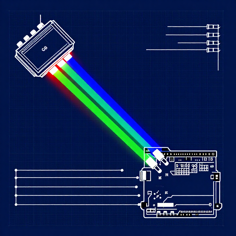
An RGB LED contains three tiny LEDs (red, green, blue) in one package. By mixing different brightness levels of each color, you can create any color in the rainbow. This experiment introduces analogWrite() for PWM output.

Parts Needed

  • 1x Arduino Uno + USB cable
  • 1x Breadboard
  • 1x RGB LED (Common Cathode)
  • 3x 330Ω Resistors
  • 5x Jumper Wires

RGB LED Pin Order (flat edge facing you): Red, Ground (longest pin), Green, Blue.

Materiali per questo passaggio:

SparkFun Inventors Kit - V3.2SparkFun Inventors Kit - V3.21 kit
Arduino Uno R3Arduino Uno R31 pezzo
BreadboardBreadboard1 pezzo
RGB LED (Common Cathode)RGB LED (Common Cathode)1 pezzo
330 Ohm Resistor330 Ohm Resistor3 pezzi
Jumper WiresJumper Wires5 pezzi

Strumenti necessari:

Computer with Arduino IDE
2

Hardware Hookup

Wiring Instructions

  1. Place the RGB LED in the breadboard. Identify pins from the flattened edge: Red, GND (longest), Green, Blue.
  2. Connect the GND pin (longest, second from left) to the GND rail.
  3. Connect the Red pin through a 330Ω resistor to Arduino Pin 9.
  4. Connect the Green pin through a 330Ω resistor to Arduino Pin 10.
  5. Connect the Blue pin through a 330Ω resistor to Arduino Pin 11.

Pins 9, 10, and 11 are all PWM-capable (marked with ~ on the board).

Materiali per questo passaggio:

RGB LED (Common Cathode)RGB LED (Common Cathode)1 pezzo
330 Ohm Resistor330 Ohm Resistor3 pezzi
BreadboardBreadboard1 pezzo
Jumper WiresJumper Wires5 pezzi
3

Arduino Code

Open the Arduino IDE and upload the following sketch to your Arduino board.

rgb_led.inoarduino
/*
SparkFun Inventor's Kit
Example sketch 03 — RGB LED

Make an RGB LED display a rainbow of colors!

Hardware connections:
  RGB LED pins (from flattened edge): RED, COMMON, GREEN, BLUE
  RED -> 330 ohm resistor -> Pin 9
  COMMON -> GND
  GREEN -> 330 ohm resistor -> Pin 10
  BLUE -> 330 ohm resistor -> Pin 11

This code is completely free for any use.
*/

const int RED_PIN = 9;
const int GREEN_PIN = 10;
const int BLUE_PIN = 11;

int DISPLAY_TIME = 10;  // milliseconds

void setup()
{
  pinMode(RED_PIN, OUTPUT);
  pinMode(GREEN_PIN, OUTPUT);
  pinMode(BLUE_PIN, OUTPUT);
}

void loop()
{
  mainColors();
  showSpectrum();
}

void mainColors()
{
  // Off
  digitalWrite(RED_PIN, LOW);
  digitalWrite(GREEN_PIN, LOW);
  digitalWrite(BLUE_PIN, LOW);
  delay(1000);

  // Red
  digitalWrite(RED_PIN, HIGH);
  digitalWrite(GREEN_PIN, LOW);
  digitalWrite(BLUE_PIN, LOW);
  delay(1000);

  // Green
  digitalWrite(RED_PIN, LOW);
  digitalWrite(GREEN_PIN, HIGH);
  digitalWrite(BLUE_PIN, LOW);
  delay(1000);

  // Blue
  digitalWrite(RED_PIN, LOW);
  digitalWrite(GREEN_PIN, LOW);
  digitalWrite(BLUE_PIN, HIGH);
  delay(1000);

  // Yellow (red + green)
  digitalWrite(RED_PIN, HIGH);
  digitalWrite(GREEN_PIN, HIGH);
  digitalWrite(BLUE_PIN, LOW);
  delay(1000);

  // Cyan (green + blue)
  digitalWrite(RED_PIN, LOW);
  digitalWrite(GREEN_PIN, HIGH);
  digitalWrite(BLUE_PIN, HIGH);
  delay(1000);

  // Purple (red + blue)
  digitalWrite(RED_PIN, HIGH);
  digitalWrite(GREEN_PIN, LOW);
  digitalWrite(BLUE_PIN, HIGH);
  delay(1000);

  // White (all on)
  digitalWrite(RED_PIN, HIGH);
  digitalWrite(GREEN_PIN, HIGH);
  digitalWrite(BLUE_PIN, HIGH);
  delay(1000);
}

void showSpectrum()
{
  int x;
  for (x = 0; x < 768; x++)
  {
    showRGB(x);
    delay(DISPLAY_TIME);
  }
}

void showRGB(int color)
{
  int redIntensity;
  int greenIntensity;
  int blueIntensity;

  if (color <= 255)
  {
    redIntensity = 255 - color;
    greenIntensity = color;
    blueIntensity = 0;
  }
  else if (color <= 511)
  {
    redIntensity = 0;
    greenIntensity = 255 - (color - 256);
    blueIntensity = (color - 256);
  }
  else
  {
    redIntensity = (color - 512);
    greenIntensity = 0;
    blueIntensity = 255 - (color - 512);
  }

  analogWrite(RED_PIN, redIntensity);
  analogWrite(GREEN_PIN, greenIntensity);
  analogWrite(BLUE_PIN, blueIntensity);
}

Materiali per questo passaggio:

Arduino Uno R3Arduino Uno R31 pezzo

Strumenti necessari:

Computer with Arduino IDE
4

Test & Experiment

What You Should See

The LED cycles through 8 solid colors (off, red, green, blue, yellow, cyan, purple, white) for 1 second each, then smoothly fades through the entire color spectrum.

Troubleshooting

  • Incorrect colors: With four pins close together, it's easy to misplace one. Double-check each connection.
  • Red too bright: The red diode is often brighter. Try a higher-value resistor on the red pin, or reduce in code: analogWrite(RED_PIN, redIntensity/3).

Experiments to Try

  • Add a potentiometer to control which color is displayed.
  • Create your own color sequences — try a "sunrise" effect (dark red → orange → yellow → white).

Materiali

6

Strumenti richiesti

1
  • Computer with Arduino IDE
Totale stimato
€119.00

CC0 Pubblico dominio

Questo progetto è rilasciato sotto CC0. Sei libero di copiare, modificare, distribuire e utilizzare quest'opera per qualsiasi scopo, senza chiedere permesso.

Supporta il Maker acquistando prodotti tramite il suo progetto dove guadagna una Commissione Maker stabilita dai venditori, oppure crea una nuova iterazione di questo progetto e includilo come collegamento nel tuo progetto per condividere i ricavi.

Discussione

(0)

Accedi per partecipare alla discussione

Caricamento commenti...