
ARTE
BELLEZZA E BENESSERE
MESTIERE
CULTURA E STORIA
DIVERTIMENTO
AMBIENTE
CIBO E BEVANDE
INGEGNERIA INVERSA
SCIENZE
SPORT
TECNOLOGIA
INDOSSABILI
The Centrifugal Pump: Speed Squared, and Why It Cannot Lift Air
Emma

Creato da

Emma

27. settembre 2026SE
1
0
0
0
0

The Centrifugal Pump: Speed Squared, and Why It Cannot Lift Air

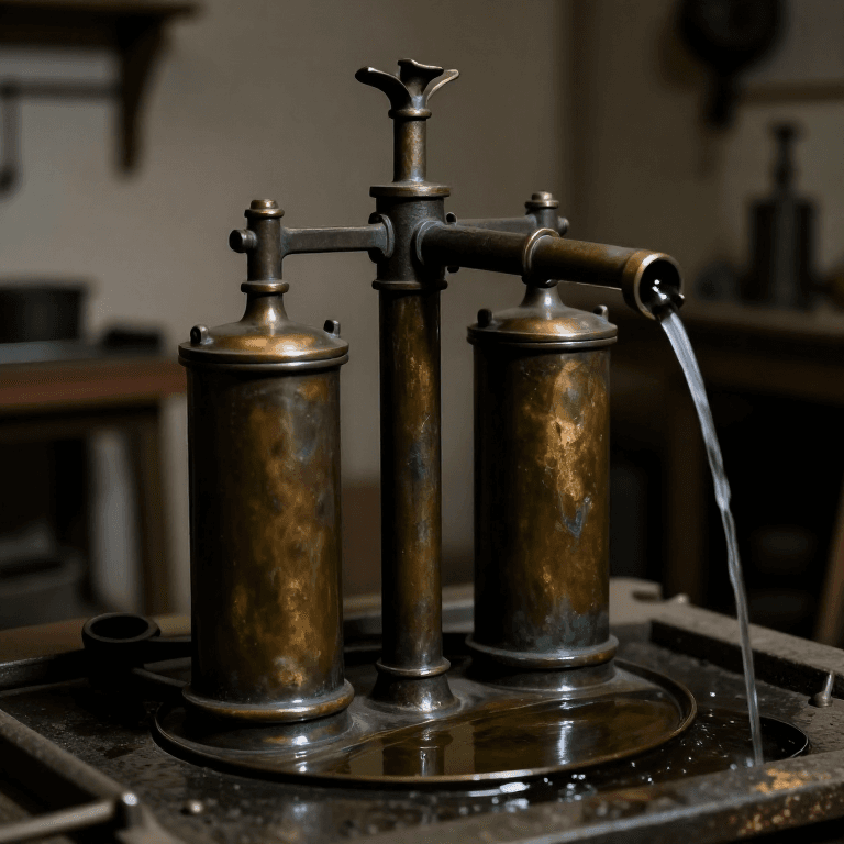
Every pump in the catalogue so far moves a fluid by trapping a pocket of it and pushing the pocket along — a piston, a gear tooth, a screw flight. The centrifugal pump traps nothing. It spins the liquid and lets the rim throw it outward into a spiral casing that turns speed into pressure. That makes it the pump of choice for water supply, heating circuits, cooling systems and most process plants: no valves, no rubbing seals on a piston, steady flow, and a single moving part. It also gives it two habits a maker has to understand before building one. The head it produces goes with the square of its speed. And it cannot pump air, so it will not pick up its own suction — which is why the foot valve on the suction pipe and the ten-metre ceiling on how high it can sit above the water are part of the machine.
Intermedio
About 5 hours

Istruzioni

1

Know the three kinds of impeller before you print one

Look at a real impeller in your hand before drawing your own. There are three kinds: - **Closed** — vanes sandwiched between two discs (shrouds). Most efficient, clogs on fibre and grit. - **Semi-open** — one shroud behind the vanes, open at the front. Tolerates some solids; the running clearance to the casing matters. - **Open** — bare vanes on a hub. Least efficient, least prone to clog, easiest to print. Now look at how the vanes curve. On almost every pump they curve **backward** — away from the direction of rotation. A straight radial vane gives more head on paper but the head rises and falls unstably with flow; backward curving trades a little head for a curve that falls steadily as flow rises, which is what lets two pumps share a pipe and one pump settle at one flow. Measure the outer diameter, the vane height at the tip and the eye diameter. Those three numbers are the design.

Materiali per questo passaggio:

Girante di pompaGirante di pompa1 pezzo

Strumenti necessari:

Calibro digitale da 6 polliciCalibro digitale da 6 pollici
RighelloRighello
2

Print the impeller and a volute, and seal the shaft

Print a **semi-open** impeller of 60 mm tip diameter with six backward-curved vanes, 10 mm tall at the eye tapering to 6 mm at the tip, on a boss that takes a steel shaft. Print the casing as a **volute**: a spiral whose gap to the impeller grows steadily round the circumference to the outlet, so the flow collected at each point has room to join what is already there without speeding up. The outlet leaves tangentially; the inlet enters on the axis, into the eye. Use PETG — it takes water indefinitely and does not creep like PLA when warm. Print a clear acrylic front cover instead of a printed one if you can: seeing the flow is half of this blueprint. Where the shaft leaves the casing, fit two O-rings in a printed gland and grease them. It will weep a little; a pump shaft seal is its own subject (see the face-seal and packing blueprints). Leave 0.5 mm between the vane tips and the front cover — tighter rubs, looser leaks flow back round the vanes.

Materiali per questo passaggio:

Filamento PETGFilamento PETG150 g
Lastra di acrilicoLastra di acrilico1 foglio
Barra di acciaio grezzaBarra di acciaio grezza1 pezzo
Assortimento di O-ringAssortimento di O-ring1 kit
Viti da metalloViti da metallo8 pezzi
Sigillante siliconicoSigillante siliconico1 pezzo

Strumenti necessari:

Stampante 3D a filamento (FDM)Stampante 3D a filamento (FDM)
Calibro digitale da 6 polliciCalibro digitale da 6 pollici
Trapano a batteriaTrapano a batteria
Serie di punte da trapanoSerie di punte da trapano
Set di chiavi a brugolaSet di chiavi a brugola
Assortimento di carta abrasivaAssortimento di carta abrasiva
3

Prime it, then measure the shut-off head against speed

Put the pump below the surface of a bucket of water, or fill the casing and suction hose by hand with a check valve at the bottom of the hose as a foot valve. Try it once dry first: the impeller will spin and nothing will come up. The notebook in step 5 shows why. Run a length of clear vinyl tube from the outlet straight up a wall and tape a tape measure beside it. Chuck the shaft in the cordless drill, hold the drill on its trigger at a steady speed and read the speed with the tachometer off a strip of reflective tape on the shaft. The water climbs the tube and stops: nothing flows, and the height is the **shut-off head**. Record it at four or five speeds. Plot head against speed squared. It should be a straight line, and it should sit at or a little above the solid-body figure of u²/2g — the volute wins back some of the tip's speed — and well below the Euler figure of u²/g. Wear safety glasses — a printed impeller that lets go at 3000 rpm throws its pieces.

Materiali per questo passaggio:

AcquaAcqua10 litri
Tubo in vinile trasparenteTubo in vinile trasparente3 metri
Valvola di ritegnoValvola di ritegno1 pezzo
Assortimento di fascette per tubiAssortimento di fascette per tubi1 set

Strumenti necessari:

Trapano a batteriaTrapano a batteria
Tachimetro digitaleTachimetro digitale
Metro a nastroMetro a nastro
SecchioSecchio
Occhiali di sicurezza trasparentiOcchiali di sicurezza trasparenti
4

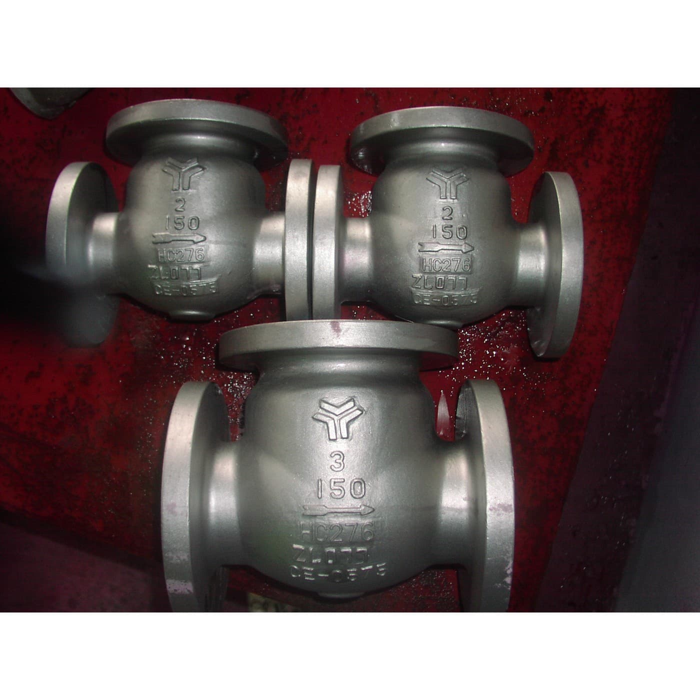
The foot valve is a check valve — this is how it works

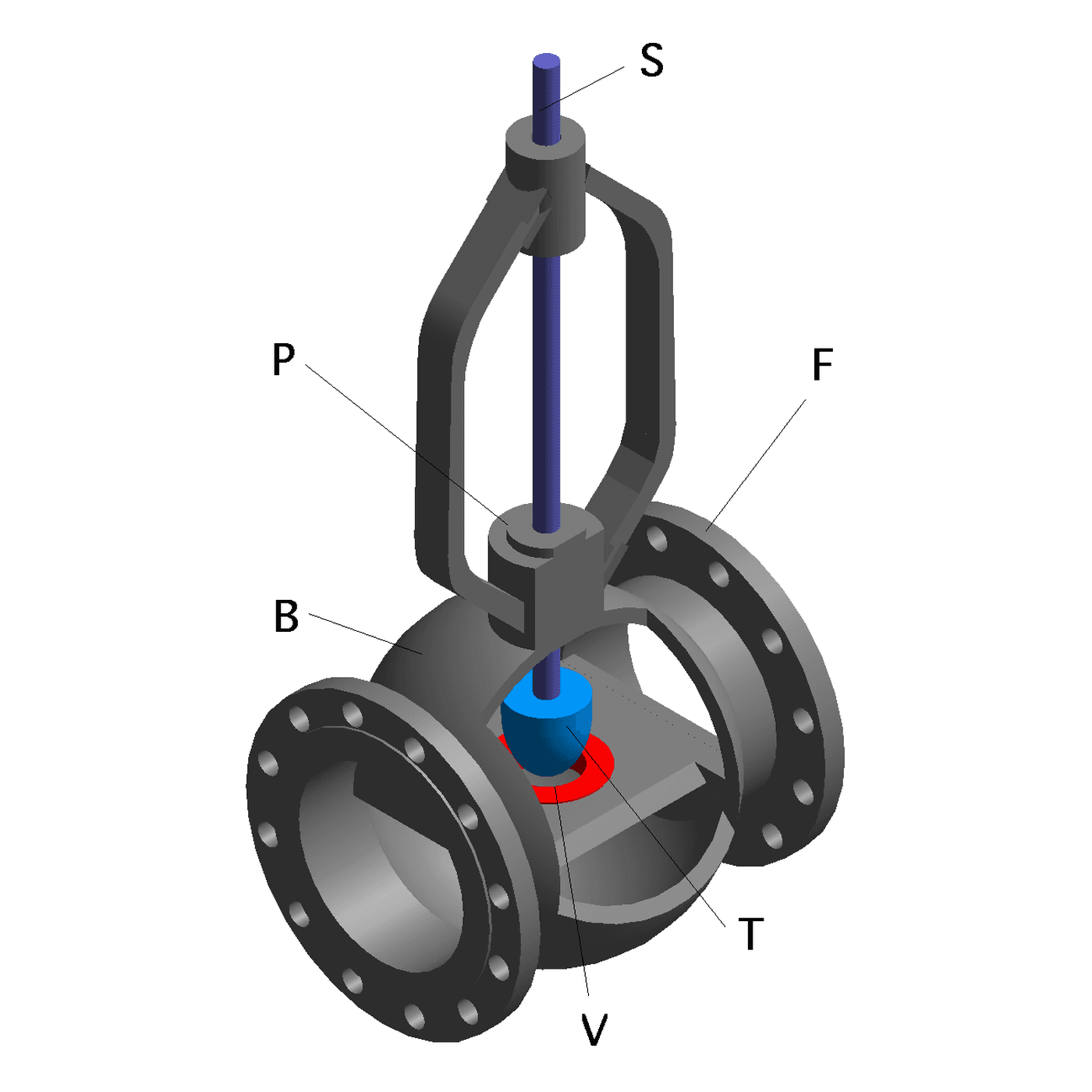
A centrifugal pump cannot hold its own prime: when it stops, the water in the suction pipe runs back down and leaves the casing full of air. The foot valve at the bottom of the suction pipe is a check valve that lets water up and not down. How it seats, and why a speck of grit on the seat empties the pipe overnight, is in the embedded blueprint.
5

Speed squared, the affinity laws, and priming

Caricamento del notebook Jupyter…
6

Throttle the outlet and draw the pump curve

Fit a ball valve in the outlet and lead the tube to a measuring jug at a fixed height. Hold the drill at one speed throughout. Wide open, time how long the jug takes to fill to a litre: that is the flow. Read the pressure on a gauge teed into the outlet before the valve: that is the head (10 kPa is about a metre of water). Close the valve a little and repeat, five or six times, down to fully closed. Plot head against flow. You will get a curve falling from shut-off head at zero flow towards zero head at maximum flow. That curve belongs to the pump. The pipe has its own curve — head needed rising with flow — and the pump runs where the two cross. Closing the valve steepens the pipe's curve and slides that crossing point up the pump's. Note what happens to the drill as you close the valve: it runs easier. A radial-flow centrifugal pump takes least power at shut-off, which is why they are started against a closed valve.

Materiali per questo passaggio:

Valvola a sfera in ottoneValvola a sfera in ottone1 pezzo
Assortimento di raccordi in PVCAssortimento di raccordi in PVC1 set
Nastro di PTFE per filettiNastro di PTFE per filetti1 rotolo

Strumenti necessari:

ManometroManometro
Brocca graduataBrocca graduata
CronometroCronometro
Trapano a batteriaTrapano a batteria
Tachimetro digitaleTachimetro digitale
Chiave regolabile a rullinoChiave regolabile a rullino
7

Suction lift, vapour pressure and cavitation

Caricamento del notebook Jupyter…
8

It runs but delivers nothing: find out why

The five faults behind almost every silent centrifugal pump, in the order to check them. Each one follows from something measured or calculated above.

Flow

Loading...
9

History and context

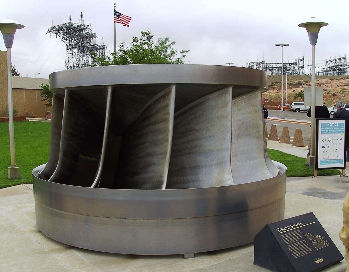
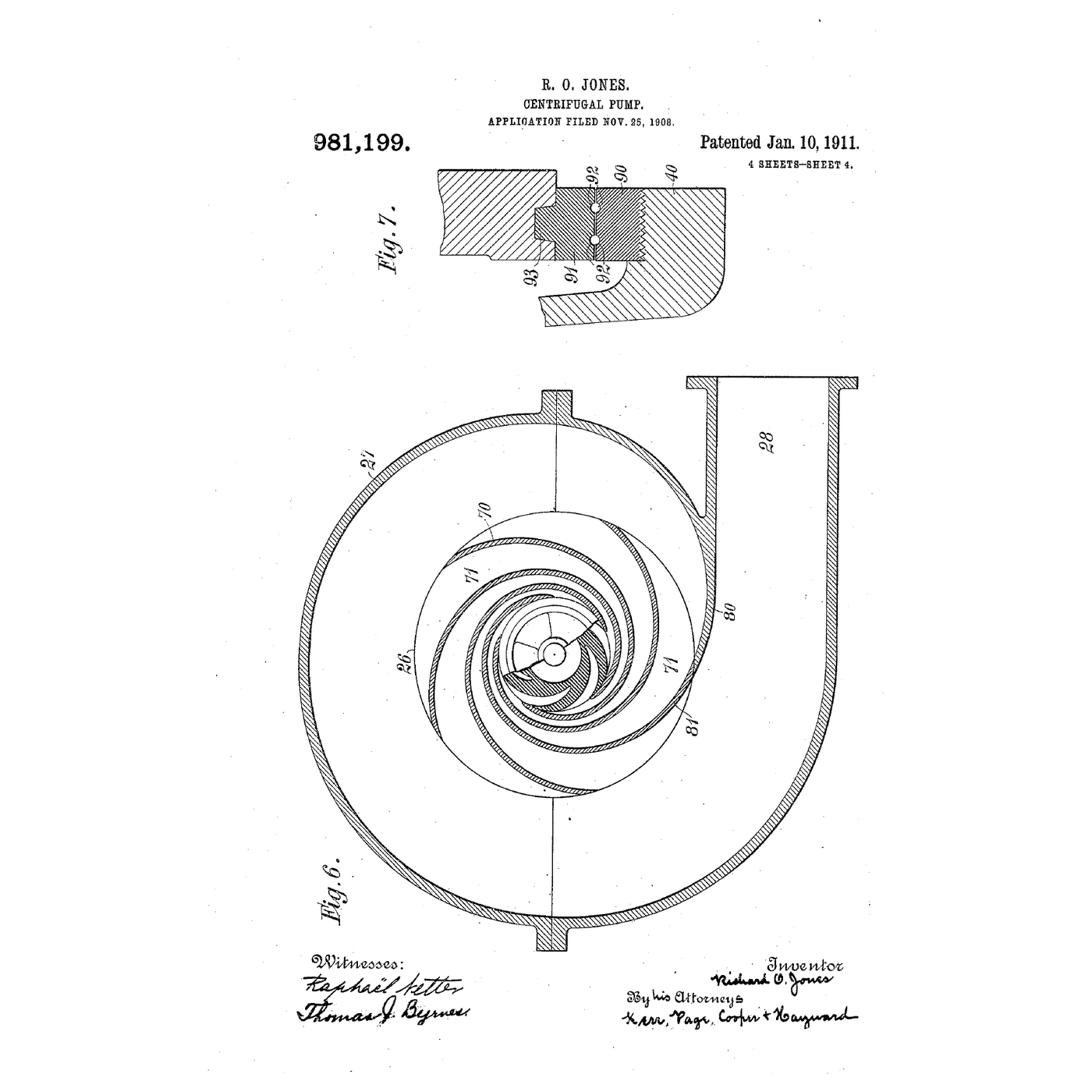
The idea of throwing water outward from a spinning wheel is old; making it efficient took until the middle of the nineteenth century. **John George Appold's pump, shown at the Great Exhibition in London in 1851, used vanes curved backward against the direction of rotation**, and the comparison with straight-vaned pumps at the same exhibition made the case for curved vanes. That is the form that stuck. No patent number is asserted here: the mechanism is what matters, and it is fully documented. The drawing shown with this blueprint is a later, fully developed form: **US 981,199, 'Centrifugal Pump', Richard O. Jones of Dayton, Ohio, assignor to the Computing Scale Company; filed 25 November 1908, granted 10 January 1911.** Water enters the eye from both sides of the impeller, leaves through a vaned *"diffusion ring"*, and is collected by a volute casing that, *"as is usual, increases from a small to a large diameter to the discharge pipe"* — the growing gap step 2 asks you to print. What made the centrifugal pump dominant came later and from outside it: the electric motor and the steam turbine, both of which run fast and smoothly — exactly the drive a machine whose head goes with speed squared wants. A reciprocating pump has to be geared down from those drives; a centrifugal pump bolts straight on. The reverse machine is the turbine. A Francis turbine is, in outline, a centrifugal pump run backward — water in at the rim, energy out at the shaft. **Honest limits.** It cannot prime itself. Its efficiency falls steeply away from the flow it was designed for. It is poor at high heads with small flows, where a piston or gear pump wins. Viscous liquids — oils, syrups — cripple it. And it cavitates if sited too high above its supply or fed hot liquid, which is why the notebook in step 7 matters more than any number on the nameplate.

Materiali

14

Strumenti richiesti

15

CC0 Pubblico dominio

Questo progetto è rilasciato sotto CC0. Sei libero di copiare, modificare, distribuire e utilizzare quest'opera per qualsiasi scopo, senza chiedere permesso.

Supporta il Maker acquistando prodotti tramite il suo progetto dove guadagna una Commissione Maker stabilita dai venditori, oppure crea una nuova iterazione di questo progetto e includilo come collegamento nel tuo progetto per condividere i ricavi.

Commenti

(0)

Accedi per partecipare alla discussione

Caricamento commenti...