コラボレーション
アート
美容とウェルネス
工芸
文化と歴史
エンターテインメント
環境
食品と飲料
リバースエンジニアリング
科学
スポーツ
テクノロジー
ウェアラブル
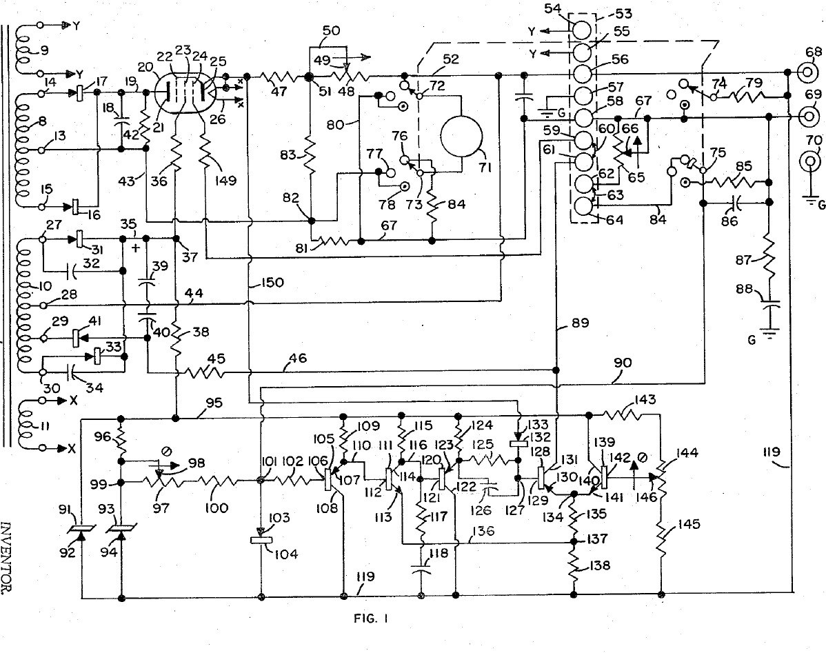


Bench Power Supply: Regulated, with Adjustable Current Limit and a Pentode Pass Tube (Gately, Forbro, US 3,243,690, 1966)
An adjustable bench supply that holds its output voltage steady and lets you set the most current it will deliver, so a circuit under test cannot be damaged. A pentode tube in series with the output is the regulator; a bridge with Zener references and a five-transistor amplifier keeps the output equal to the setting of one knob. A meter switch reads volts, amps, and the current limit, which can be set without disturbing the voltage.
Result: a regulated DC bench supply with adjustable current limiting.
Source: J. R. Gately (Forbro Design), US 3,243,690 (1966). Unknown: all component values and the output rating. Picture: the patent drawing.
上級者
Unknown
手順
1
1
Wire the mains side
Wire the mains side
In a case, wire the power cord through a switch and a fuse to the primary of a transformer with four secondaries, and put a neon lamp across the primary to show the supply is on. One secondary (6.3 V) goes to two terminals for outside use, one heats the pentode, one is the main supply and one the bias supply. Ours: the case. Not given: the other winding voltages.
このステップの材料:
 アルミ筐体箱1 case
 プラグ付きコード1 個
 トグルスイッチ1 個
 ヒューズ1 個
 降圧トランス1 four secondaries
 ネオン表示ランプ1 個
 バインディングポスト2 6.3 V terminals
必要な工具:
 ハンドドリル
 ドライバーセット
2
2
Build the rectifiers
Build the rectifiers
Rectify the centre-tapped main winding with two rectifiers and smooth it with a capacitor. From the bias winding make two more supplies: one through two rectifiers with by-pass capacitors to a smoothing capacitor, for the pentode's screen and the reference circuit; the other through one rectifier and a capacitor, for the pentode's grid bias. Not given: the values.
このステップの材料:
 ダイオード5 rectifiers
 電解コンデンサ3 smoothing
 コンデンサキット1 by-pass
 はんだ線1 as needed
必要な工具:
 はんだごて
3
3
Fit the pass tube and reference
Fit the pass tube and reference
Put the pentode in series with the positive output: plate to the main supply, cathode through two current-sensing resistors (one fixed, one adjustable) to the + output terminal; suppressor tied to the cathode, screen fed through a resistor. Build the reference: a Zener fed through a resistor feeds a second Zener at constant current, giving a fixed voltage. Against it set two resistors and the voltage-control variable resistor: the output voltage is proportional to that resistor's setting. Not given: the tube type and values.
このステップの材料:
 五極管1 series pass tube
 ツェナーダイオード2 個
 電気抵抗1 セット
 レオスタット2 voltage control, current-limit rangeバインディングポスト2 output + and -はんだ線1 as needed
必要な工具:
はんだごて4
4
Build the error amplifier and current limit
Build the error amplifier and current limit
Build a five-transistor amplifier that drives the pentode's grid to keep the bridge balanced: a PNP emitter follower, an NPN stage, a PNP emitter follower with a resistor-capacitor roll-off against oscillation, a PNP driver whose base resistor has a capacitor across it for quick response, and an NPN clamp whose base is set by a potentiometer. Feed the voltage across the current-sensing resistors to the driver's base through a diode: above the limit it takes over and turns the pentode down. Choose the fixed sensing resistor to limit at about 125 % of rated current, trim with the potentiometer, and use the adjustable one to set lower limits. Not given: the transistor types and values.
このステップの材料:
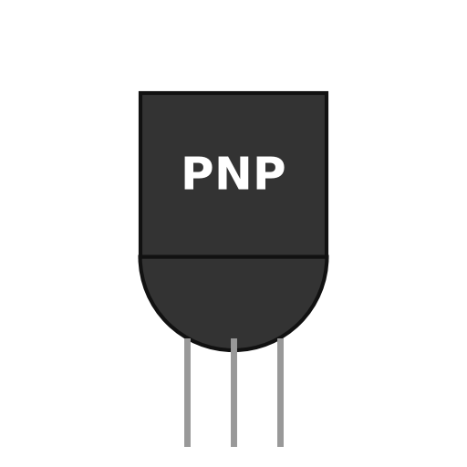 PNPトランジスタ3 個
 NPN トランジスタ2 個ダイオード1 個
 可変抵抗器1 個コンデンサキット1 roll-off, speed-up電気抵抗1 セットはんだ線1 as needed
必要な工具:
はんだごて5
5
Fit the meter and use it
Fit the meter and use it
Fit a meter with a four-pole, three-position switch. Position 1 reads output volts through a multiplier resistor; position 2 reads current across a shunt in the negative line; position 3 (spring-return) puts a load resistor across the output and swaps a fixed resistor for the voltage control, so you can turn the limit control until the current limits at the value you want, without touching the voltage setting. Release the switch and use the supply.
このステップの材料:
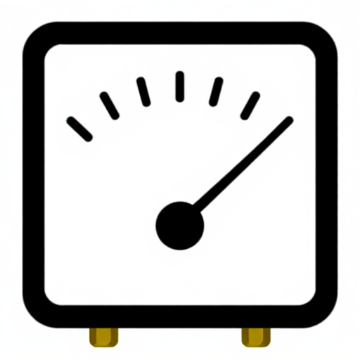 可動コイル形パネルメーター1 個
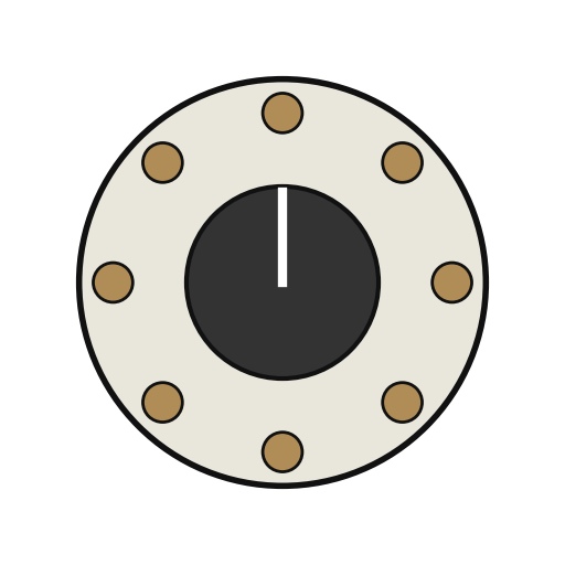 ロータリースイッチ1 4-pole, 3-position電気抵抗1 multiplier, shunt, load resistors
 不明な材料1 terminal strip
必要な工具:
はんだごてドライバーセット材料
21- 1 caseプレースホルダー
- 1 個プレースホルダー
- プレースホルダー
- 1 個プレースホルダー
- 1 four secondariesプレースホルダー
- 1 個プレースホルダー
- プレースホルダー
- 1 個プレースホルダー
- 3 smoothingプレースホルダー
- 1 roll-off, speed-upプレースホルダー
- 3 as neededプレースホルダー
- 1 series pass tubeプレースホルダー
- 2 個プレースホルダー
- 1 multiplier, shunt, load resistorsプレースホルダー
- 2 voltage control, current-limit rangeプレースホルダー
- 3 個プレースホルダー
- 2 個プレースホルダー
- プレースホルダー
- プレースホルダー
- 1 4-pole, 3-positionプレースホルダー
- 1 terminal stripプレースホルダー
この設計図で作るもの

CC0 パブリックドメイン
このブループリントはCC0で公開されています。許可を求めずに、自由にコピー、修正、配布、あらゆる目的で使用できます。
メイカーを応援するには、ブループリント経由で製品を購入してください。メイカーには メイカーコミッション がベンダーにより設定されています。または、このブループリントの新しいイテレーションを作成し、自分のブループリントにコネクションとして含めて収益を共有できます。