アート
美容とウェルネス
工芸
文化と歴史
エンターテインメント
環境
食品と飲料
グリーンフューチャー
リバースエンジニアリング
科学
スポーツ
テクノロジー
ウェアラブル
翻訳済み
BLUEPRINT NFT

点滅するLED — あなたの最初のArduinoプロジェクト
古典的な最初の電子工学プロジェクト!Arduino、ブレッドボード、抵抗器、および単一のLEDを使用して点滅するLED回路を構築します。完全な初心者向け — はんだ付けは不要です。
手順
1
1
コンポーネントを集める
コンポーネントを集める
以下にリストされたすべてのコンポーネントを集めてください。はんだ付けは不要です — すべてがブレッドボードに接続します。
このステップの材料:
 SparkFun Inventor's Kit - V3.21 キット
Arduino Uno R31 個
5mm LED (any color)1 個
 220 ohm Resistor (1/4W)1 個
Breadboard1 個
Jumper Wires (Male-to-Male)2 個
USB-B Cable1 個
必要な工具:
Computer with Arduino IDE
2
2
回路図
回路図
信号はArduino Pin 13 → 220Ω抵抗器(R1) → LED(D1) → GNDから流れます。抵抗器はLEDを保護するために電流を制限します。
このステップの材料:
Arduino Uno R31 個
5mm LED (any color)1 個
220 ohm Resistor (1/4W)1 個3
3
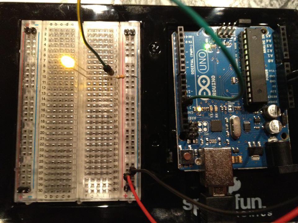
配線する
配線する
- LEDをブレッドボードに挿入します — 長い脚(アノード +)を1行に、短い脚(カソード −)を次の行に挿入します。
- 220Ω抵抗の1本の脚をLEDカソードと同じ行に挿入します。もう一方の脚を別の行に挿入します。
- ジャンパーワイヤをLEDアノード行からArduino Pin 13に接続します。
- ジャンパーワイヤを抵抗の空いている行からArduino GNDに接続します。
このステップの材料:
5mm LED (any color)1 個
220 ohm Resistor (1/4W)1 個Breadboard1 個
Jumper Wires (Male-to-Male)2 個
4
4
Blinkコードをアップロード
Blinkコードをアップロード
USBでArduinoを接続します。Arduino IDEを開き、Tools → Board → Arduino Unoを選択し、コードを貼り付けてUploadをクリックします。
blink.inoarduino
このステップの材料:
Arduino Uno R31 個
USB-B Cable1 個
必要な工具:
Computer with Arduino IDE
5
5
PCB レイアウト(参考)
PCB レイアウト(参考)
これは回路を PCB レイアウトで示しています。このプロジェクトでは必要ありませんが、ブレッドボードで完璧に動作します。ただし、実際のボードとして製造された場合、同じ回路がどのように見えるかを示しています。
6
6
テストと実験
テストと実験
LEDが点滅しますか?おめでとうございます!ハードウェアをプログラミングしました。
トラブルシューティング:
次の実験:
トラブルシューティング:
- LEDが点灯しませんか? LEDを反転させてください — 長い脚をPin 13に向けて。
- LEDが常に点灯していますか?コードが正常にアップロードされたか確認してください。
- 何も起こりませんか?配線がStep 2のスキーマティックと一致することを確認してください。
次の実験:
delay()の値を変更して点滅速度を制御します- Pin 12に2番目のLEDを追加します
- RGB LEDに置き換えます(SIK Circuit 3を参照)
材料
7- ¥164
- プレースホルダー
見積もり合計
¥164Related blueprints
Other builds that share materials, tools, or techniques with this one.

Using a Shift Register — SIK Circuit 14electronics/active
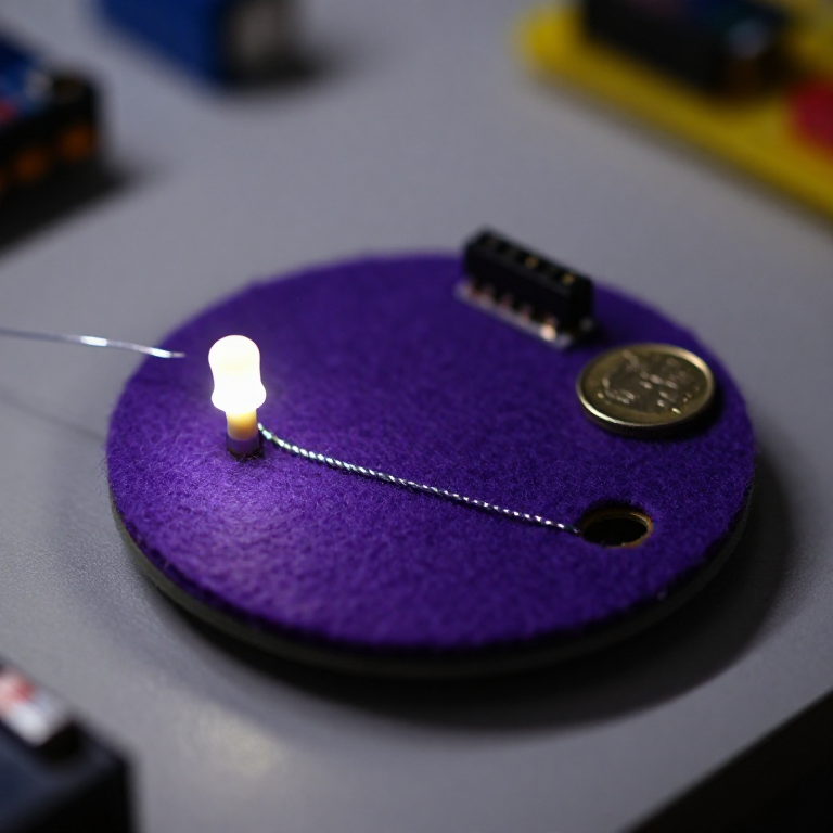
Blinking an LED with LilyPad Arduinoelectronics

Making Charcoal — The First Chemical Processmaterials

The Spinning Jenny — Multi-Spindle Yarn Productiontextiles
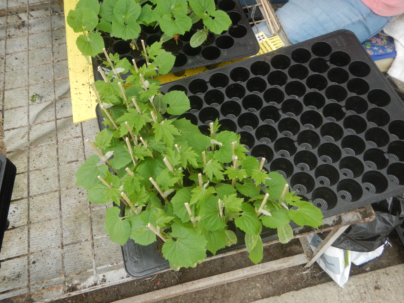
Starting Seeds Indoors — Raising Seedlings for a Head Start
Driving a Motor — SIK Circuit 12electronics/electromech
CC0 パブリックドメイン
このブループリントはCC0で公開されています。許可を求めずに、自由にコピー、修正、配布、あらゆる目的で使用できます。
メイカーを応援するには、ブループリント経由で製品を購入してください。メイカーには メイカーコミッション がベンダーにより設定されています。または、このブループリントの新しいイテレーションを作成し、自分のブループリントにコネクションとして含めて収益を共有できます。