Building a Roman Odometer — The Gear-Driven Distance Measurer
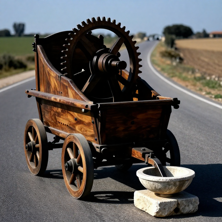
The Roman odometer (hodometer, from Greek ὁδόμετρον — 'road measurer') is a gear-driven device mounted on a cart wheel that automatically counts the distance travelled in Roman miles. It was described in detail by Vitruvius in 'De Architectura' (Book X, Chapter IX, ~25 BCE) and by Hero of Alexandria. The principle: the cart wheel rotates as it travels, driving a gear train at a ratio of exactly 400:1. After 400 wheel revolutions (= one Roman mile, the mille passuum or 'thousand paces' of 1,480 metres), a single gear completes one full revolution, releasing one pebble from a hopper into a collecting bowl. At journey's end, the number of pebbles in the bowl equals the number of Roman miles travelled.
The Roman mile (mille passuum) was precisely defined as 1,000 double paces (a passus = one stride of approximately 1.48 metres). Roman road engineers measured new road construction using surveyors' measuring wheels called perambulators, and the odometer served the same function for carts and vehicles on established roads. Julius Caesar's troops reportedly used measuring wheels to survey Gaul and Britain, and odometer readings appear in Roman administrative documents as the standard unit for road distances — the numbers on Roman milestones were set by odometer measurement.
The device Vitruvius describes was never confirmed archaeologically until recent decades. No physical Roman odometer has been unambiguously identified, though fragments from Alexandria and Rome have been proposed. All modern reconstructions are based entirely on Vitruvius' text, which is clear enough in principle but ambiguous about several mechanical details. The device represents a sophisticated application of gear reduction — the same engineering principle used in clock movements, automobile transmissions, and electric motor gearboxes — adapted to solve a practical surveying problem with materials available in the 1st century BCE.
手順
Calculate the wheel circumference for exactly 400 revolutions per mile
Calculate the wheel circumference for exactly 400 revolutions per mile
The entire odometer's accuracy depends on the cart wheel having the correct circumference. One Roman mile = 1,480 metres (measured by Vitruvius as 8 stades of 185 metres each). For the gear train to count exactly 1 mile per 400 wheel revolutions, the wheel circumference must be exactly 1,480 m / 400 = 3.70 metres. The diameter corresponding to this circumference is 3.70 / π = 1.178 metres — approximately 117.8 cm diameter.
This is a specific, non-standard wheel size. If you are fitting the odometer to an existing cart with a different wheel diameter, you must recalculate the gear ratio to give 400:1 for that wheel's actual circumference, or adjust the wheel diameter by adding or removing wooden rim material. Measure your wheel circumference precisely by rolling it along a straight line and marking 10 complete revolutions, then dividing the total distance by 10. Use the actual measured circumference to calculate the exact gear ratio needed: required ratio = measured circumference / (1,480 m / desired pebbles-per-interval).
必要な工具:
 Hemp Cord
Design the gear reduction train for 400:1 ratio
Design the gear reduction train for 400:1 ratio
A 400:1 gear reduction cannot be achieved in a single gear pair without one gear being impractically large relative to the other (a 400-tooth gear meshed with a 1-tooth gear would have a gear 400 times the pinion diameter — impossible). Instead, cascade two gear stages: Stage 1 reduces 400 by a factor of 20 (the first gear drives a second at 20:1), Stage 2 reduces the Stage 1 output by another factor of 20 (20 × 20 = 400 total). This requires four gear wheels: two large gears and two small pinions.
Vitruvius describes the reduction differently — using a worm gear (a helical screw that drives a wheel) rather than spur gears, giving a large single-stage reduction. A worm gear with a 400-tooth worm wheel on the cart axle, driven by a one-start worm, gives 400:1 directly and is simpler to build than two stages of spur gears. Choose whichever is more practical: spur gears if you can cut gear teeth accurately; worm gear if you have a lathe or can carve a helical thread in wood. Vitruvius' own text describes a worm gear arrangement.
Cut the primary drive wheel from hardwood
Cut the primary drive wheel from hardwood
The primary drive wheel is mounted on the cart axle and rotates with the cart wheel — one revolution of the cart wheel = one revolution of the primary drive wheel. It has 400 teeth (for a single-stage worm drive reduction) or 20 teeth (for the first stage of a two-stage spur gear reduction). For the worm gear design: cut a large hardwood disc approximately 40 cm diameter and 3 cm thick. Mark 400 equal divisions around the circumference using a geometric dividing method — wrap a strip of paper around the disc circumference, mark its exact length, fold it into 400 equal segments, unwrap and use the fold marks to lay out the tooth positions.
For a 400-tooth wheel at 40 cm diameter, each tooth pitch (centre-to-centre) is π × 40 cm / 400 = 0.314 cm — about 3 mm. Teeth at this pitch are small but cuttable with a fine-toothed saw and a chisel. Cut each tooth space to 1.5 mm depth. The teeth do not need to be precise gear-geometry shapes for a worm drive — simple rectangular notches that the worm thread can engage are sufficient, as the worm thread contacts each tooth over a wide face rather than at a precise involute contact point.
このステップの材料:
 Hardwood Block3 個
必要な工具:
 Hand Saw
 Awl
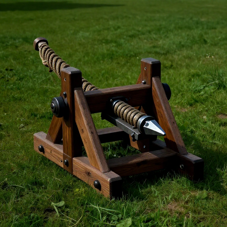
AwlCarve the worm gear drive from hardwood
Carve the worm gear drive from hardwood
The worm is a cylindrical shaft with a continuous helical thread on its surface, oriented so that one full revolution of the worm shaft advances the worm wheel by exactly one tooth. For a 400-tooth worm wheel, one revolution of the worm advances the wheel 1/400 of a full turn. The worm shaft is mounted at right angles to the worm wheel axle, with its thread engaging the wheel teeth on the top surface of the worm wheel rim.
Carve the worm from a dense hardwood dowel approximately 3 cm diameter and 10 cm long. To cut the helical thread, mark the thread path by wrapping a paper triangle around the dowel (the same technique as marking the Archimedes' screw helix) — the triangle's hypotenuse angle determines the thread pitch. The thread pitch equals the worm wheel tooth pitch = 3 mm for the 400-tooth 40 cm wheel. Use a sharp knife to cut the thread groove to approximately 1.5 mm depth along the marked helix path. Round the thread crest (the top of the helical ridge) slightly to prevent stress concentration. This is demanding carving work — the thread must be continuous and consistent in depth all the way around the worm.
このステップの材料:
Hardwood Block1 個必要な工具:
 Sharp Knife
Mount the gear train on the cart frame
Mount the gear train on the cart frame
The primary drive wheel is mounted rigidly on the cart axle between the cart body and one wheel — it must rotate with the axle, not spin freely on it. Bore a square hole through the drive wheel centre to match the cross-section of the cart axle (most Roman cart axles were square or octagonal in cross-section to prevent the wheel from spinning on the axle). This is the critical mounting: if the drive wheel slips on the axle, the odometer counts nothing — every slip is uncounted distance.
The worm shaft is mounted in two wooden bearing brackets fixed to the inside of the cart body, positioned so the worm thread engages the worm wheel teeth with the correct mesh depth — approximately 1.5 mm of tooth engagement. The worm shaft must be parallel to the cart's longitudinal axis (perpendicular to the wheel axle). Adjust the bracket positions until the worm turns freely when the cart wheel is spun by hand, with a slight resistance from the gear engagement (barely perceptible friction = correct meshing; tight resistance = overmeshed; no resistance with clicking = undermeshed and jumping teeth).
このステップの材料:
Hardwood Block2 個 Iron Nails20 個
必要な工具:
 Hammer (2 kg)
Build the pebble-dropping mechanism
Build the pebble-dropping mechanism
At the output end of the gear train (the slow end — one revolution per mile), mount a disc with a single hole or notch at its periphery. Above this disc, mount a hopper containing smooth pebbles (rounded river pebbles, 8–10 mm diameter) held up by a sliding floor. Each time the hole in the rotating disc passes underneath the hopper outlet, one pebble drops through onto a collecting shelf that slopes into a bowl or cup below. The pebble count in the bowl at journey's end = number of miles travelled.
The pebble drop mechanism must reliably release exactly one pebble per revolution of the output disc. If pebbles jam in the hopper outlet (too many try to drop at once) or skip (none drop when the hole aligns), the count is wrong. Size the hopper outlet hole to exactly one pebble diameter: 10 mm for 10 mm pebbles. The disc hole must be at least 12 mm diameter to allow the pebble to fall through freely. Test the mechanism by rotating the output disc by hand through many revolutions, counting pebbles dropped against disc revolutions — they must match one-for-one consistently.
このステップの材料:
Hardwood Block1 個Build a protective enclosure for the gear train
Build a protective enclosure for the gear train
The gear train must be protected from road dust, water, and mechanical damage from road debris thrown up by the wheel. Build a wooden enclosure (a box with a lid) around the entire gear assembly, mounted to the cart underside or inside the cart body. The enclosure needs inspection ports — removable panels or a hinged lid — to access the pebble bowl without disassembling the cart, and to re-lubricate the gear mesh periodically.
Line the interior of the enclosure with cloth to catch any pebbles that bounce off the collecting bowl. Without cloth lining, an uneven road surface causes pebbles to bounce and scatter when dropped, making the count unreliable. Pad the bowl interior with cloth for the same reason. Seal the enclosure joints with pine pitch to keep dust and water out of the gear mesh — water causes the wooden gears to swell and jam; dust accelerates wear.
このステップの材料:
Hardwood Block2 個Iron Nails15 個Calibrate on a known-distance road section
Calibrate on a known-distance road section
After assembly, calibrate the odometer on a road section of known length — ideally a section between two Roman milestones (if using the device for historical research) or between two surveyed marks (if building for practical use). Drive the cart at a constant pace over the known distance, then count the pebbles. If the pebble count matches the expected miles exactly, calibration is complete. If the count is high (too many pebbles), the wheel is smaller than calculated and is covering less distance per revolution — the ratio must be adjusted by reducing the tooth count on the primary wheel. If the count is low, the wheel is larger than calculated.
Each pebble discrepancy over a 5-mile test section indicates a 20% error in the wheel circumference measurement or the gear ratio. For construction surveying accuracy, the odometer should be within 2% of true distance — equivalent to no more than 1 pebble discrepancy over a 50-mile journey. Vitruvius' design, with a correctly sized wheel and accurately cut gears, achieved this accuracy on Roman roads, as evidenced by the consistent agreement between ancient road distance records and modern archaeological measurements between Roman road stations.
Lubricate the gear mesh with tallow
Lubricate the gear mesh with tallow
The worm gear mesh experiences significant sliding friction — the worm thread slides along the worm wheel teeth rather than rolling as spur gear teeth do. Without lubrication, this sliding wears both surfaces rapidly, causing the gear mesh to loosen (increasing backlash and reducing accuracy) and eventually seizing. Apply rendered tallow or beeswax to the worm thread surfaces before each journey, working it into the tooth mesh by hand-rotating the drive wheel through several revolutions before mounting.
Re-lubricate the worm after every 20 miles of use (every 20 pebbles). If the gear engagement noise changes from a smooth swishing to intermittent clicking or grinding, remove the enclosure cover and re-lubricate immediately — the change in sound indicates the lubricant film has broken down and metal-on-metal (or wood-on-wood) contact is occurring. Unlike later clock mechanisms which use oil, the worm gear in a dust-exposed road environment performs better with grease (tallow) than with oil, which picks up dust particles and becomes an abrasive paste.
Use the odometer for road construction measurement
Use the odometer for road construction measurement
The Roman road administration used measured distances for milestone placement, road tax assessment (based on distance hauled), military logistics (march-time calculations), and administrative boundary delineation. Equip the odometer cart with a starting rod (a marker placed at the journey origin) and a recording tablet. Before departure, count the pebbles in the bowl and note the starting count (typically zero after emptying). At each milestone position, note the pebble count and drive an alignment peg into the road verge — this records both the distance and the position for milestone carvers to follow.
The accuracy of the Roman road network's distance records validates the odometer concept: surviving itineraries (route guides with distances between stations) match archaeological measurements to within 2–5% over hundreds of kilometres. This level of accuracy requires the odometer to function correctly across thousands of wheel revolutions, on roads with varying surfaces (paved via militaris, gravel, compacted earth), in different wheel-slip conditions (wet paved road vs dry earth), and through seasonal temperature variation that swells or shrinks the wooden wheel rim — all of which the Vitruvian design handled acceptably in Roman practice.
Variation — water-clock integration for travel time
Variation — water-clock integration for travel time
An extension proposed by some historians of technology (though not documented in ancient sources) is integrating the odometer with a water clock (clepsydra) to measure travel time simultaneously with distance, allowing calculation of average travel speed. If the worm gear's output shaft also drives a pointer on a dial, the pointer can indicate both distance (via the pebble counter) and position-in-cycle (for speed calculation if combined with a known time interval from the water clock). This dual-measurement capability mirrors the modern vehicle odometer and speedometer combination.
No such combined device is attested in the ancient sources, but the mechanical elements were all available in the 1st century BCE: the odometer gear train, the water clock, and connecting gear shafts. The Antikythera Mechanism demonstrates that the ancient Greeks had no conceptual barrier to combining multiple measurement functions in a single mechanical device — only the practical demand for a combined odometer-clock was apparently absent, or the device existed but did not survive. This is a suitable extension project for a maker who has built both the odometer and the clepsydra water clock separately.
Accuracy limitations and sources of error
Accuracy limitations and sources of error
The Roman odometer has three principal sources of measurement error. First, wheel slip: on wet or muddy roads, the cart wheel skids rather than rolling, and the skid distance is not counted — the odometer under-reads on bad roads. Second, wheel deformation: a wooden wheel rim absorbs moisture and expands in wet weather, changing its circumference and hence the distance per revolution without the gear ratio changing to compensate. A 1% change in wheel circumference produces 1% error in all subsequent distance readings. Third, gear wear: as the worm and worm wheel teeth wear, the effective ratio changes slightly, accumulating error over time.
Roman road engineers compensated for wheel slip by using smooth-paved sections (via militaris) for calibration measurement and applying the calibration factor to unpaved sections. They compensated for wheel wear by periodically re-calibrating against known milestone distances and adjusting the gear ratio or wheel size accordingly. These systematic calibration practices explain how Roman road itineraries achieved 2–5% accuracy despite using wooden wheels and unprecision gears — the errors were managed by regular recalibration rather than eliminated at the design stage, a pragmatic engineering philosophy that remains valid in modern metrology.
接続ブループリントの材料
関連ブループリント
これらのブループリントは知識を共有しています — 技術、材料、原理
Related blueprints
Other builds that share materials, tools, or techniques with this one.
CC0 パブリックドメイン
このブループリントはCC0で公開されています。許可を求めずに、自由にコピー、修正、配布、あらゆる目的で使用できます。
メイカーを応援するには、ブループリント経由で製品を購入してください。メイカーには メイカーコミッション がベンダーにより設定されています。または、このブループリントの新しいイテレーションを作成し、自分のブループリントにコネクションとして含めて収益を共有できます。