アート
美容とウェルネス
工芸
文化と歴史
エンターテインメント
環境
食品と飲料
リバースエンジニアリング
科学
スポーツ
テクノロジー
ウェアラブル
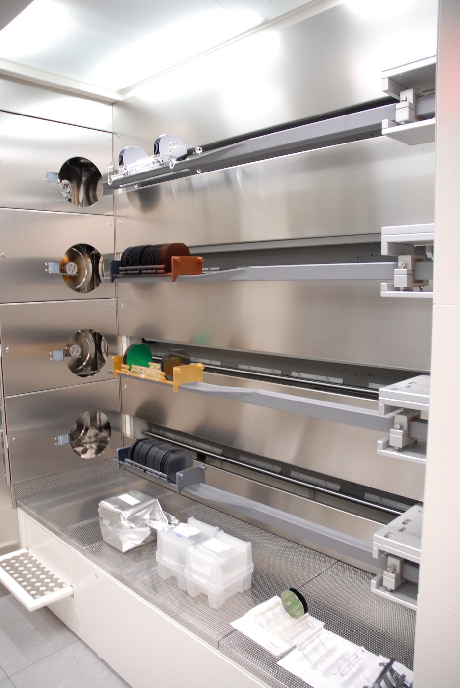


Diffusion Doping
You have spent two blueprints removing every impurity from silicon down to parts per billion. Now you put some back — deliberately, in a known element, in a known amount, in a known place.
That is doping, and the quantities are the strange part. A useful doping level is around one part in a million to one part in ten million. Silicon has about 5 times 10^22 atoms per cubic centimetre, so a typical doping of 10^16 atoms per cubic centimetre means roughly one dopant atom for every five million silicon atoms. That vanishingly small contamination changes the conductivity by six orders of magnitude, and it is why the purification had to reach parts per billion first: an accidental impurity at one part in a hundred million would be a tenth of your signal.
Add phosphorus or arsenic, each with five valence electrons where silicon has four, and the spare electron is loosely bound and becomes a mobile negative carrier — n-type. Add boron with three, and the missing electron leaves a hole that moves like a positive carrier — p-type. Put a p region next to an n region and you have a diode. Put three regions in a row and you have a transistor. Everything is that.
The question this blueprint answers is HOW the dopant gets in and how far it goes. Before ion implantation arrived in the 1970s the answer was diffusion: heat the silicon to around 1000 degrees with a source of dopant at the surface, and let thermal motion carry the atoms in. The maths is Fick's second law, the profiles are the error function and the Gaussian, and the shape of those profiles determines where the junction lands.
You cannot run a diffusion furnace. What you will do is measure a real diffusion coefficient in a system you can watch, fit the same equations to it, and then apply them to the silicon case with real published constants — so the numbers you take away are the numbers a process engineer uses.
中級者
4 hours
手順
1
1
Watch diffusion happen and measure its coefficient
Watch diffusion happen and measure its coefficient
Diffusion is one of the few pieces of solid-state physics you can watch with your eyes, provided you choose a system slow enough to see and coloured enough to follow.
THE SETUP. Make up a gel: 1.5 percent agar in water, heated to dissolve and poured into a set of identical clear tubes or a shallow tray, then left to set. Agar gel is mostly water, so molecules diffuse through it at nearly their free-solution rate, but it holds them still against convection — and convection is what ruins this measurement in plain water. What you are removing is bulk flow, so that what remains is pure diffusion.
Place a source at one end: a small crystal of potassium permanganate, which is intensely purple and diffuses visibly, or methylene blue. Keep the whole thing at a steady temperature and out of draughts.
THE MEASUREMENT. Photograph the tube against a ruler at fixed intervals — every 15 minutes for the first two hours, then hourly. What you are tracking is how far the colour front has moved.
The result that matters, and it surprises people: the distance does not grow linearly with time. It grows as the SQUARE ROOT of time. Double the time and the front advances by only 1.41 times as far. Quadruple it for double the distance.
This is not a property of agar or permanganate. It is the fundamental character of all diffusion, and it comes straight from Fick's second law. A diffusing atom performs a random walk, and the mean distance covered by a random walk grows as the square root of the number of steps. Every diffusion in this blueprint — dopant into silicon at 1000 degrees, oxygen through silicon dioxide in the last one — obeys the same square-root law.
Plot your front position against the square root of elapsed time. It should be a straight line. Its slope gives you the diffusion coefficient D, in the same units and by the same arithmetic a process engineer uses for boron in silicon.
DO IT TWICE, AT TWO TEMPERATURES. Run one tube at room temperature and one in a warm water bath at 40 degrees. The warm one is markedly faster, and that temperature dependence is the second thing you need. Diffusion coefficients follow an Arrhenius law, D = D0 exp(-Ea/kT), so a modest rise in temperature produces a large rise in D. In silicon the activation energies are three to four electron volts, which means the diffusion coefficient changes by a factor of ten for every hundred degrees or so. That extreme sensitivity is exactly why diffusion furnaces are controlled to a degree across a metre of tube, and why the thermal budget is the tyrant of the whole process.
このステップの材料:
 寒天粉末100 gram
 過マンガン酸カリウム——KMnO450 gram
 メチレンブルー25 gram
 透明塩ビ管1 metre
 蒸留水5 リットル
必要な工具:
 マグネチックスターラー付きホットプレート
 実験用温度計
 デジタルノギス 6インチ
 ストップウォッチ
 実験用保護めがね
 耐薬品手袋
耐薬品手袋2
2
Fick, the erfc and the Gaussian, and where the junction lands
Fick, the erfc and the Gaussian, and where the junction lands
Jupyter ノートブックを読み込み中…
必要な工具:
 デスクトップパソコン
3
3
Show a doped region conducts differently — a four-point probe
Show a doped region conducts differently — a four-point probe
Doping is invisible. A doped wafer looks exactly like an undoped one, so the only way to know it worked is electrical, and the standard instrument is a four-point probe. Build one; it is four needles and some arithmetic, and it is the measurement every fab makes on every wafer.
WHY FOUR POINTS AND NOT TWO. Measure resistance with two probes and you measure your sample plus both contact resistances plus the leads, and on a semiconductor the metal-to-silicon contact resistance can easily exceed the thing you are trying to measure. The four-point method separates the jobs: force a known current through the OUTER two probes, and measure the voltage across the INNER two with a high-impedance voltmeter that draws essentially no current. No current through the voltage probes means no voltage dropped across their contact resistance, so what you read is the sample alone.
BUILD IT. Four sewing needles or spring-loaded pogo pins in a row, at equal spacing — 1 to 2 mm, and the spacing must be equal and known. Mount them in a drilled acrylic block so they stand parallel and land together. Wire the outer pair to a constant-current source and the inner pair to a multimeter on its most sensitive DC voltage range. A simple current source is a 9 V battery in series with a large resistor, and you measure the actual current with a second meter rather than assuming it.
THE ARITHMETIC. For a thin layer on an insulating or opposite-type substrate, and with the probe spacing much smaller than the sample, the sheet resistance is
Rs = 4.532 x V / I ohms per square
That 4.532 is pi divided by the natural log of 2, and it falls out of the geometry of current spreading from a point contact into a thin sheet. It assumes an infinite sheet; correction factors exist for small samples and you should apply them if your sample is less than about ten probe spacings across.
"Ohms per square" is a genuinely useful unit and worth understanding. The resistance of a rectangular patch of a uniform sheet depends only on the RATIO of its length to its width, not on its absolute size — a 1 mm square and a 1 cm square of the same sheet have the same resistance. So sheet resistance times the number of squares along a conductor gives its resistance, and circuit designers lay out resistors by counting squares.
WHAT TO MEASURE. You cannot make doped silicon, so measure things that demonstrate the method and its sensitivity: a sheet of aluminium foil, a piece of graphite-coated paper, a commercial ITO-coated glass slide, and if you can get one, a real doped silicon wafer or even a solar cell with the contacts removed. Compare your readings against published sheet resistances.
Then convert. If you know the layer thickness t, the bulk resistivity is rho = Rs x t. And for silicon there is a published relationship between resistivity and dopant concentration — the Irvin curves — so a sheet resistance measurement plus a junction depth from the previous step gives you the average doping. That chain, from a voltmeter reading to an atom count, is how the industry knows what is in its wafers.
このステップの材料:
 アクリル板1 square metre
 アルミ箔1 個
 黒鉛粉末100 gram
 抵抗器キット1 セット
必要な工具:
 ラボグレード・デジタルマルチメータ
 はんだステーション
 コードレスドリルデジタルノギス 6インチ
 ドリルビットセット
 手縫い針
手縫い針 バレルジャック付き 9 V 電池
4
4
Compendium — the questions that follow
Compendium — the questions that follow
WHY DOES A DOPANT ATOM HAVE TO SIT ON A LATTICE SITE? Because only a substitutional atom — one that has replaced a silicon atom in the lattice and bonded to its four neighbours — has the spare electron or missing bond that makes it electrically active. A dopant sitting in the gaps between atoms, interstitially, is electrically inert. After ion implantation, which fires atoms in ballistically and leaves most of them in the wrong place along with a badly damaged lattice, an ANNEAL is required to let the atoms hop onto proper lattice sites and the damage heal. Activation, the fraction that ends up substitutional, is a real process parameter and it is not 100 percent.
WHAT IS SOLID SOLUBILITY AND WHY DOES IT CAP THE SURFACE? There is a maximum concentration of a given dopant that silicon will hold in solution at a given temperature — for boron and phosphorus it is in the low 10^20 atoms per cubic centimetre near 1100 degrees. Beyond it the excess precipitates out as a separate phase and is electrically dead. That is the ceiling on the Cs in the erfc profile, and it is why you cannot simply dope harder to get lower resistance.
WHY DID ION IMPLANTATION REPLACE DIFFUSION? Three reasons, all about control. Dose is measured directly as electrical charge arriving, so it is precise to a fraction of a percent rather than depending on furnace chemistry. Depth is set by beam energy rather than by time and temperature, so it decouples from the thermal budget. And the lateral spread is far smaller, which is what let feature sizes fall below a micrometre. Diffusion is still used for deep, cheap, non-critical layers.
WHY IS ARSENIC USED FOR SHALLOW N-TYPE AND PHOSPHORUS FOR DEEP? Look at the numbers in the notebook: arsenic's diffusion coefficient is roughly two orders of magnitude below phosphorus at the same temperature. That makes arsenic sluggish, which is a liability when you want a deep well and exactly what you want for a shallow source or drain that must not move during later heating. The dopant is chosen for its diffusivity as much as its type.
WHAT IS EMITTER PUSH? A real and initially baffling effect: a heavy phosphorus diffusion locally accelerates the diffusion of boron beneath it, so the base region under an emitter is pushed deeper than the same diffusion elsewhere on the wafer. The cause is that the heavy doping injects a supersaturation of silicon self-interstitials, and boron diffuses by riding on those interstitials. Dopants interact through the defects they create, so profiles cannot always be superposed.
WHY IS THE THERMAL BUDGET CUMULATIVE? Because every dopant moves during every hot step, not just its own. A drive-in for the third diffusion also drives the first and second deeper. Process engineers therefore track the total of D times t across the whole sequence, and the ordering is forced: deep, slow-diffusing layers first, shallow ones last, and every step after a critical one must be cooler or shorter. It is a scheduling problem as much as a chemical one.
材料
9- 100 gramプレースホルダー
- 50 gramプレースホルダー
- 25 gramプレースホルダー
- 1 metreプレースホルダー
- 5 リットルプレースホルダー
- 1 square metreプレースホルダー
- 1 個プレースホルダー
- 100 gramプレースホルダー
- プレースホルダー
必要な工具
13- プレースホルダー
- プレースホルダー
- プレースホルダー
- プレースホルダー
- プレースホルダー
- プレースホルダー
- プレースホルダー
- プレースホルダー
- プレースホルダー
- 1 vendor sell this, none ship to you yetプレースホルダー
- プレースホルダー
- プレースホルダー
- プレースホルダー
関連ブループリント
これらのブループリントは知識を共有しています — 技術、材料、原理


CC0 パブリックドメイン
このブループリントはCC0で公開されています。許可を求めずに、自由にコピー、修正、配布、あらゆる目的で使用できます。
メイカーを応援するには、ブループリント経由で製品を購入してください。メイカーには メイカーコミッション がベンダーにより設定されています。または、このブループリントの新しいイテレーションを作成し、自分のブループリントにコネクションとして含めて収益を共有できます。