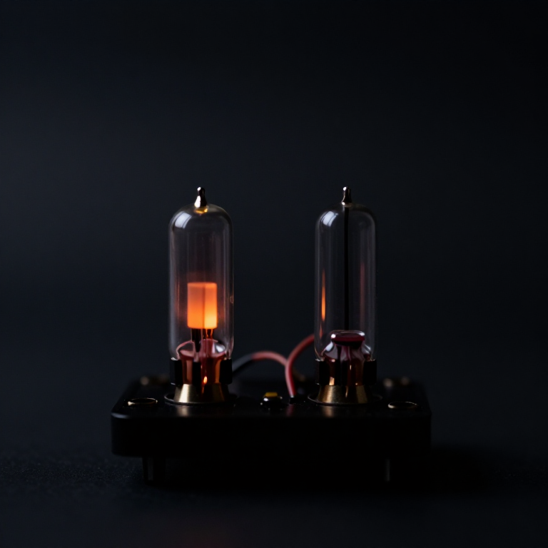


The Eccles-Jordan Flip-Flop
手順
Cross-couple two amplifiers and watch it latch
Cross-couple two amplifiers and watch it latch
Build it with two transistors — the topology is identical to the 1918 valve original and runs at 5 V instead of 200.
- Wire two common-emitter stages, each with a collector resistor.
- Cross-couple: transistor A’s collector to transistor B’s base through a resistor, and B’s collector to A’s base.
- Fit an LED on each collector.
- Power up and observe. Then briefly ground one base and release it.
One LED lights and the other does not, and it STAYS that way after you remove your hand. Ground the other base and the state flips and stays flipped.
The mechanism is a race that has already been won. If A conducts, it pulls B’s base low, so B is off, so B’s collector is high, which keeps A’s base high, which keeps A on. Each state reinforces itself, so both are stable and there is no third option.
Which state it lands in at power-up is genuinely unpredictable — decided by tiny mismatches in the two transistors and by noise. That is why real systems have a RESET line: a memory that starts in an unknown state is not memory yet.このステップの材料:
 トランジスター詰め合わせ1 キット
 抵抗器キット1 キット
 表示用LEDセット1 セット
 ユニバーサル基板1 個
 接続用電線1 reel
必要な工具:
 はんだステーション
 オシロスコープ
 ラボグレード・デジタルマルチメータ
 可変直流電源
The SR latch state table, including the forbidden one
The SR latch state table, including the forbidden one
Trace all four input combinations on your circuit and confirm each. The first one — both inputs inactive — is the whole point: the circuit does nothing, and doing nothing is how it remembers.
The fourth is the interesting failure. Asserting SET and RESET together demands the output be both 1 and 0; the circuit obeys as best it can, and on release the two halves race. Which one wins is decided by propagation delays of a few nanoseconds, so the same circuit can settle differently on identical inputs.
That is metastability, and it never fully goes away — it is pushed into a smaller and smaller time window as circuits get faster. Every clocked system has setup and hold times precisely because data changing too close to a clock edge can put a flip-flop into this race, and a synchroniser is two flip-flops in series giving the first one a whole clock period to make up its mind.Flow
必要な工具:
 デスクトップパソコン
Add a clock, and make it count
Add a clock, and make it count
Upload and open the serial monitor. Part 1 drives the latch you built and — crucially — reads Q back 500 ms after every input has gone idle. If Q is unchanged, the circuit stored a bit with nothing holding it there.
Part 2 models four toggle flip-flops in a chain. Watch the toggles column: most clocks flip only one stage, but every so often a carry ripples through all four. That variable propagation is the ripple counter's defect — the count is briefly wrong while the carry travels, so you must not read it mid-ripple.
このステップの材料:
 マイコンボード1 個トランジスター詰め合わせ1 キット抵抗器キット1 キット接続用電線1 reel
必要な工具:
 Arduino IDE を入れたパソコンオシロスコープラボグレード・デジタルマルチメータはんだステーション
Measure setup, hold and the metastable window
Measure setup, hold and the metastable window
Find the timing rules that every synchronous system obeys, by violating them.
- Clock a D-type flip-flop from a generator and feed data from a second generator, slightly offset in frequency so the data edge slowly walks across the clock edge.
- Watch the output on the oscilloscope, triggered on the clock.
- Find the region where the output sometimes takes noticeably longer to settle, or lands on the wrong value.
There is a window around the clock edge where the flip-flop cannot decide quickly — data must be stable for a setup time BEFORE the edge and a hold time AFTER it, and inside that window the output resolution time stretches unpredictably.
It is worth being precise about why this cannot be engineered away: the flip-flop is deciding which of two stable states to fall into, and if pushed exactly to the boundary it sits near the balance point. Nothing forces it off quickly. You cannot make the probability zero — only make the window small and give the circuit time. This is a genuine physical limit, not a manufacturing defect.このステップの材料:
 ロジックICの詰め合わせ1 キットユニバーサル基板1 個
必要な工具:
オシロスコープ ファンクションジェネレータ
 信号発生器ラボグレード・デジタルマルチメータ
One bit costs two transistors — now scale it
One bit costs two transistors — now scale it
Count the cost of memory, because that number shaped every computer built before 1970.
- Count the components in your latch: transistors, resistors, connections.
- Multiply by 8 for a byte, by 1024 for a kilobyte.
- Estimate power: measure the current your single latch draws and scale it.
A flip-flop is fast and expensive. Two active devices per bit means a kilobyte of flip-flop memory needs some sixteen thousand transistors and draws real power continuously — in the valve era it meant sixteen thousand valves, each with a heater, each eventually failing.
That is why early machines had tiny fast register memory and desperately sought something cheaper for bulk storage. Mercury delay lines, Williams tubes and magnetic cores were all answers to this one economic problem, and each traded speed or convenience for cost per bit.
The flip-flop never went away — it is still what a CPU register and a cache cell are made of, because nothing beats it for speed. It simply stopped being how you store megabytes. That split between a small fast expensive store and a large slow cheap one is the memory hierarchy, and it exists in every computer today for exactly the reason you have just measured.必要な工具:
ラボグレード・デジタルマルチメータデスクトップパソコン材料
7- 1 キットプレースホルダー
- プレースホルダー
- 1 セットプレースホルダー
- 1 個プレースホルダー
- 1 reelプレースホルダー
- 1 個プレースホルダー
- 1 キットプレースホルダー
関連ブループリント
これらのブループリントは知識を共有しています — 技術、材料、原理

CC0 パブリックドメイン
このブループリントはCC0で公開されています。許可を求めずに、自由にコピー、修正、配布、あらゆる目的で使用できます。
メイカーを応援するには、ブループリント経由で製品を購入してください。メイカーには メイカーコミッション がベンダーにより設定されています。または、このブループリントの新しいイテレーションを作成し、自分のブループリントにコネクションとして含めて収益を共有できます。