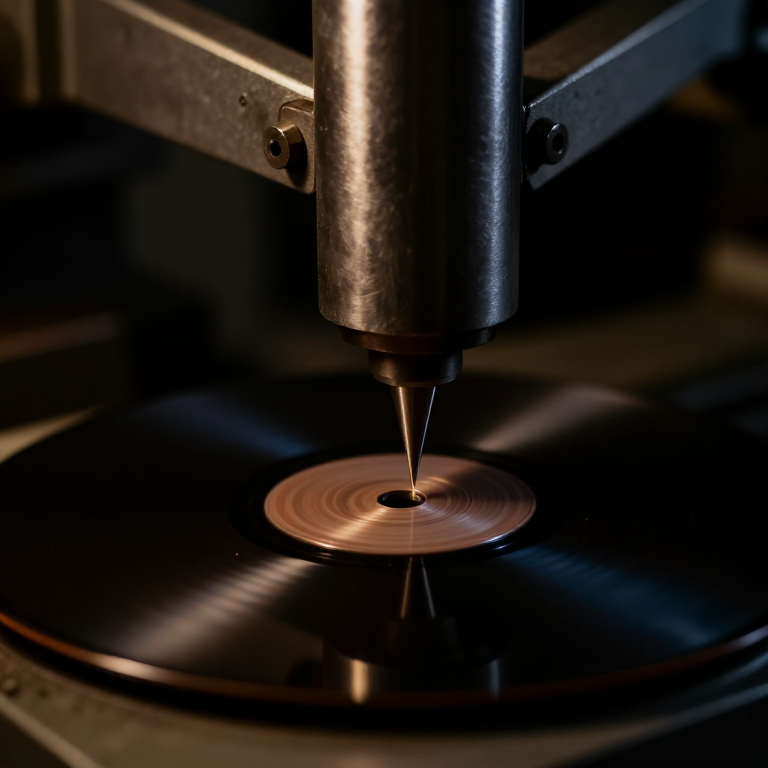


Electrical Recording
手順
Record acoustically first, to feel the problem
Record acoustically first, to feel the problem
You cannot appreciate what electrical recording fixed without meeting the constraint.
- Build a simple acoustic recorder: a horn ending in a diaphragm with a stylus attached.
- Cut a groove in a soft wax or acetate disc rotating on a turntable.
- Try recording a loud voice close to the horn, then a quiet one further away.
- Try recording two people at once.
Only the loudest source close to the horn registers at all. The sound's own energy has to move the stylus through the medium, so there is no gain anywhere in the system and no way to balance sources. Performers were arranged by loudness rather than by musical sense, brass players stood at the back, and string sections were replaced by a Stroh violin with its own horn because a normal violin simply did not record.
This is why pre-1925 records sound the way they do. The limitation was never the disc — it was that no amplification existed anywhere in the chain.このステップの材料:
 アクリル板1 枚
 非常用マイラーブランケット1 個
 アルミ丸棒1 個
必要な工具:
 ヤスリセット
 デジタルノギス 6インチ
 コードレスドリル
 ストップウォッチ
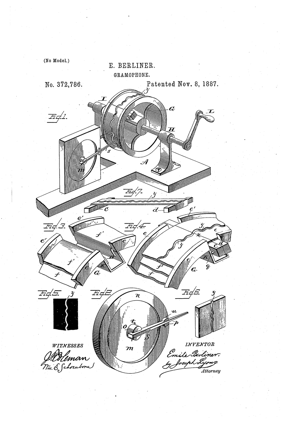
Build an electromagnetic cutter head
Build an electromagnetic cutter head
A moving-coil motor again, now driving a stylus instead of a cone.
- Mount a small coil in a magnetic gap, as in the moving-coil microphone.
- Attach a cutting stylus rigidly to the coil.
- Provide a compliant suspension that centres the stylus but allows lateral movement.
- Add mechanical damping — a rubber or felt element bearing on the moving assembly.
Damping is what separates a cutter head from a loudspeaker motor. An undamped moving system rings at its resonance, and a resonance in a cutter head is carved permanently into the groove. Maxfield and Harrison's contribution was as much about applying electrical filter theory to the mechanical system — treating springs and masses as circuit elements — as about adding amplification.
That analogy, mechanical systems analysed as electrical networks, was new in 1925 and is now standard in loudspeaker and transducer design. The batch's underlying idea is that the chain became electrical in its thinking as well as its signal path.このステップの材料:
 エナメル被覆銅線1 巻
 フェライトビーズセット1 キット
 真鍮丸棒1 個
必要な工具:
デジタルノギス 6インチヤスリセット ラボグレード・デジタルマルチメータ
 万力(ベンチバイス)
Insert the amplifier and take control of the level
Insert the amplifier and take control of the level
Gain is the thing acoustic recording never had.
- Connect microphone, amplifier and cutter head in a chain.
- Record the quiet source that failed acoustically, turning the gain up.
- Record two sources at different distances and balance them by moving the microphone rather than the performers.
- Record with the gain deliberately too high and inspect the groove.
このステップの材料:
 オーディオアンプ1 キット
 電解コンデンサーキット1 キット
必要な工具:
 デジタルオシロスコープラボグレード・デジタルマルチメータデジタルノギス 6インチ
Measure the frequency range you gained
Measure the frequency range you gained
Put a number on the improvement rather than asserting it.
- Feed a swept tone through the electrical chain and cut a test groove.
- Play it back and record the level at each frequency.
- Do the same acoustically, driving the horn from a loudspeaker at constant level.
- Plot both curves together.
このステップの材料:
 方眼紙1 pad
必要な工具:
 DDS 信号発生器デジタルオシロスコープラボグレード・デジタルマルチメータ
The chain becomes electrical, and history
The chain becomes electrical, and history
Joseph Maxfield and Henry Harrison at Bell Telephone Laboratories developed the electrical recording system, licensed to Victor and Columbia in 1925. The industry converted within about a year, and the change was so audible that record companies advertised it directly — Victor’s “Orthophonic” and Columbia’s “Viva-tonal” were marketing names for the same underlying Bell system.
It is a systems achievement rather than a single invention. The condenser microphone existed from 1916, the valve amplifier from the 1910s, the electromagnetic cutter was straightforward. What Bell Labs contributed was analysing the whole chain — including the mechanical parts — as one electrical network with a designed response, and the discipline of matching each stage to the next.
What it did to the recording business. Acoustic recording could not capture an orchestra, a piano, or a soft voice. Electrical recording could, and within a few years the entire classical repertoire was being recorded, crooning became possible as a vocal style because a singer no longer had to shout into a horn, and the microphone became an instrument in its own right.
Its honest limits at the time: the disc was still a disc, so playing time stayed at around four minutes, surface noise remained high, and the frequency range, though doubled, was still modest. Those three problems drive the rest of this batch — magnetic tape solves duration and editing, the LP solves playing time and noise, and stereo adds a dimension none of them had.
材料
9- 1 枚プレースホルダー
- プレースホルダー
- 1 個プレースホルダー
- 1 巻プレースホルダー
- 1 キットプレースホルダー
- 1 個プレースホルダー
- プレースホルダー
- 1 キットプレースホルダー
- 1 padプレースホルダー
関連ブループリント
これらのブループリントは知識を共有しています — 技術、材料、原理


CC0 パブリックドメイン
このブループリントはCC0で公開されています。許可を求めずに、自由にコピー、修正、配布、あらゆる目的で使用できます。
メイカーを応援するには、ブループリント経由で製品を購入してください。メイカーには メイカーコミッション がベンダーにより設定されています。または、このブループリントの新しいイテレーションを作成し、自分のブループリントにコネクションとして含めて収益を共有できます。