コラボレーション
アート
美容とウェルネス
工芸
文化と歴史
エンターテインメント
環境
食品と飲料
リバースエンジニアリング
科学
スポーツ
テクノロジー
ウェアラブル
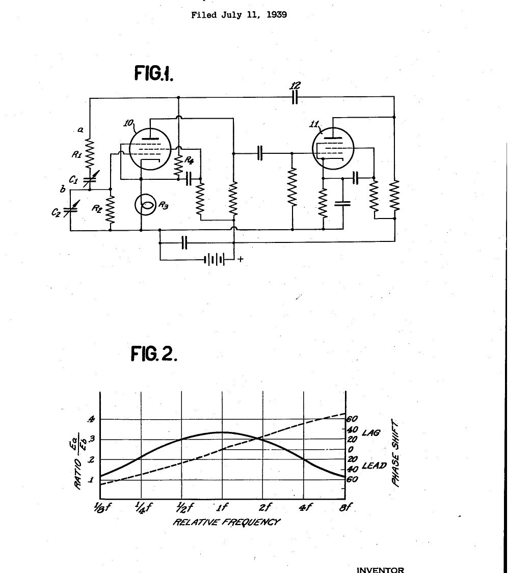


Function Generator: Resistance-Capacity Tuned Audio Oscillator with Lamp Amplitude Control (Hewlett, US 2,268,872, 1942)
The first Hewlett-Packard product: a test oscillator tuned by resistors and capacitors instead of coils. Two valve amplifiers feed their output back to their input through a series and a parallel R-C pair, which passes only one frequency in phase, so the circuit oscillates there. A second, negative feedback path through a small lamp holds the amplitude steady: as the swing grows the lamp warms, its resistance rises and the gain falls. One dial covers ten to one in frequency.
Result: a sine-wave signal generator covering 20 to 20,000 cycles in three ranges, about 0.25 % distortion.
Source: W. R. Hewlett, US 2,268,872 (1942). Unknown: valve types and component values. Picture: the patent drawing.
上級者
Unknown
手順
1
1
Build the two-stage amplifier
Build the two-stage amplifier
Wire two amplifying valves in cascade with resistance-capacity coupling, the first's anode to the second's grid, run as class A amplifiers. Not given: valve types, values, the supplies. Ours: pentode valves in sockets.
このステップの材料:
 五極管2 個
 真空管ソケット2 個
 電気抵抗1 セット
 コンデンサキット1 coupling and by-pass
 アルミ筐体箱1 case
 はんだ線1 as needed
必要な工具:
 はんだごて
2
2
Fit the tuning network
Fit the tuning network
From the second valve's anode, through a coupling capacitor, feed back to the first valve's grid through a resistor R1 in series with a variable capacitor C1, with a resistor R2 and variable capacitor C2 from the grid to ground. Make R1 = R2 and C1 = C2: the frequency is then 1/(2 pi R C), set by the capacitors, giving 10 to 1 on one dial. For the capacitors use a four-gang tuning capacitor with its sections paired in parallel. Switch three sets of resistors in for the ranges 20-200, 200-2000 and 2000-20,000 cycles. Ours: a rotary switch.
このステップの材料:
 可変コンデンサー(空気誘電体)1 four-gang電気抵抗1 three sets of R1, R2
 ロータリースイッチ1 range switch
必要な工具:
はんだごて ドライバーセット
3
3
Fit the lamp feedback and use it
Fit the lamp feedback and use it
From the same output, through the coupling capacitor, feed back to the first valve's cathode across a resistor R4 and a small incandescent lamp R3. As the oscillation grows, the lamp heats, its resistance rises, the negative feedback increases and the gain falls, so the amplitude settles below the point of grid current with no clipping. The negative feedback also steadies the gain against valve and supply changes. Take the output from the terminals; Hewlett's test unit held its output within about 10 % over 20-20,000 cycles, with about 0.25 % distortion and under 0.1 % frequency shift with supply changes.
このステップの材料:
 電球1 small incandescent lamp電気抵抗1 R4
 バインディングポスト2 output
必要な工具:
 直流電源はんだごて
材料
10- 2 個プレースホルダー
- 2 個プレースホルダー
- 1 R4プレースホルダー
- 1 coupling and by-passプレースホルダー
- 1 caseプレースホルダー
- 1 as neededプレースホルダー
- 1 four-gangプレースホルダー
- 1 range switchプレースホルダー
- 1 small incandescent lampプレースホルダー
- プレースホルダー
この設計図で作るもの

CC0 パブリックドメイン
このブループリントはCC0で公開されています。許可を求めずに、自由にコピー、修正、配布、あらゆる目的で使用できます。
メイカーを応援するには、ブループリント経由で製品を購入してください。メイカーには メイカーコミッション がベンダーにより設定されています。または、このブループリントの新しいイテレーションを作成し、自分のブループリントにコネクションとして含めて収益を共有できます。