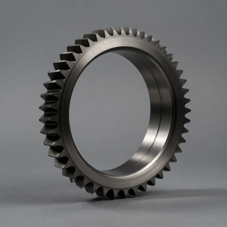


Harmonic Drive
Gearing had been a rigid-body business since antiquity: hard teeth on hard wheels, and the whole art was in cutting them accurately and keeping them apart. Every gear train carried a tax — backlash, the small free play needed so teeth can enter and leave mesh without jamming. For most machines that is harmless. For a robot arm or a satellite antenna it is intolerable, because the output can wander by that amount under no load at all.
Musser's departure was to make one of the gears flexible. A thin steel cup with external teeth — the flexspline — sits inside a rigid internally-toothed ring. An elliptical wave generator inside the cup deforms it into an oval, pushing its teeth into full engagement at the two ends of the long axis and pulling them clear everywhere else.
The flexspline has two fewer teeth than the ring. So one full turn of the wave generator walks the flexspline backwards by exactly two teeth. With 200 teeth on the ring, that is a 100:1 reduction in one stage, in a component barely thicker than a saucer.
It also has almost no backlash, because at any moment 30% or more of the teeth are engaged — not the two or three of a conventional pair — and they are held in contact by the flexing, not resting in clearance.
C. Walton Musser, US 2,906,143, "Strain Wave Gearing", filed 21 March 1955, granted 29 September 1959; the principle was publicly announced in 1957, which is the date most sources quote.
手順
Measure backlash in an ordinary gear pair
Measure backlash in an ordinary gear pair
Mesh two spur gears. Lock the output. Rock the input back and forth by hand and measure the free movement with a dial indicator on the input.
Record it. Expect something between 0.1° and 1° depending on quality.
That is lost motion — the output does not know the input moved. In a machine tool it is a positioning error; in a robot arm it is the arm drifting under its own weight.
必要な工具:
 ダイヤルゲージ
Model the three parts
Model the three parts
Print or cut the three elements:
Circular spline — rigid ring, internal teeth, say 100.
Flexspline — thin flexible cup, external teeth, 98. Two fewer, always.
Wave generator — an ellipse that fits inside the flexspline and deforms it.
Assemble: wave generator inside flexspline inside circular spline.
このステップの材料:
 PLA フィラメント200 g
必要な工具:
 万力(ベンチバイス)
Watch which teeth are engaged
Watch which teeth are engaged
Mark the two ends of the wave generator's long axis. Turn it slowly and watch the teeth.
Expect engagement only near those two ends, and the engaged zone to travel round the ring as the generator turns.
Count roughly how many teeth are in contact. It should be tens, not two. That is where the load capacity and the stiffness come from — the load is shared across a third of the teeth at once.
Turn it once and count backwards
Turn it once and count backwards
Mark one flexspline tooth. Turn the wave generator exactly one full revolution and find your mark.
Expect it to have moved two teeth backwards — opposite to the direction you turned.
Ratio = (teeth on flexspline) / (difference) = 98/2 = 49:1 from three parts. Backwards output is not a defect; it falls out of the arithmetic, and it is why harmonic drives are specified with the sign noted.
Measure its backlash and compare
Measure its backlash and compare
Lock the output, rock the input, measure as in step 1.
Expect it to be very much smaller — near zero on a real steel unit, small even on a printed one.
Then feel for the trade-off: torsional wind-up. Load the output and the input rotates slightly even though no tooth has slipped. The flexspline is a spring, so the drive is stiff-but-not-rigid, and that compliance is the price of the flexing that removed the backlash.
History & Context
History & Context
The patent. US 2,906,143, "Strain Wave Gearing", C. Walton Musser, filed 21 March 1955, granted 29 September 1959. The widely-quoted 1957 is the year the principle was announced, not a patent date — worth separating, since all three years appear in print as "the" date.
Why it is a genuine departure. Conventional gearing treats parts as rigid and designs clearance in. Musser designed a part to deflect elastically as part of the mechanism. It is applied elastic dynamics rather than rigid-body kinematics, which is why it reads as strange the first time and why it produces properties — near-zero backlash, huge single-stage ratio, coaxial input and output — that no rigid train gives together.
Musser was not a gear specialist. He held over 200 patents across mechanical engineering, physics, chemistry and biology. That is context, not trivia: the harmonic drive is the kind of idea that comes from someone not fully trained in the assumptions of the field.
Where it is used. Almost every industrial robot joint, spacecraft mechanisms, telescope drives, machine tool indexing. The Apollo Lunar Roving Vehicle used harmonic drives in its wheels — a good illustration of the appeal, since mass and volume mattered more there than almost anywhere.
The honest limitations. The wind-up in step 5 is real and must be modelled in a control loop. The flexspline is a fatigue part — it is deliberately flexed millions of times, so it has a finite life in a way a rigid gear does not. And efficiency is moderate, typically 70–90%, because a great many teeth sliding into and out of mesh costs more friction than two teeth rolling.
材料
1- 200 gプレースホルダー
接続ブループリントの材料

CC0 パブリックドメイン
このブループリントはCC0で公開されています。許可を求めずに、自由にコピー、修正、配布、あらゆる目的で使用できます。
メイカーを応援するには、ブループリント経由で製品を購入してください。メイカーには メイカーコミッション がベンダーにより設定されています。または、このブループリントの新しいイテレーションを作成し、自分のブループリントにコネクションとして含めて収益を共有できます。