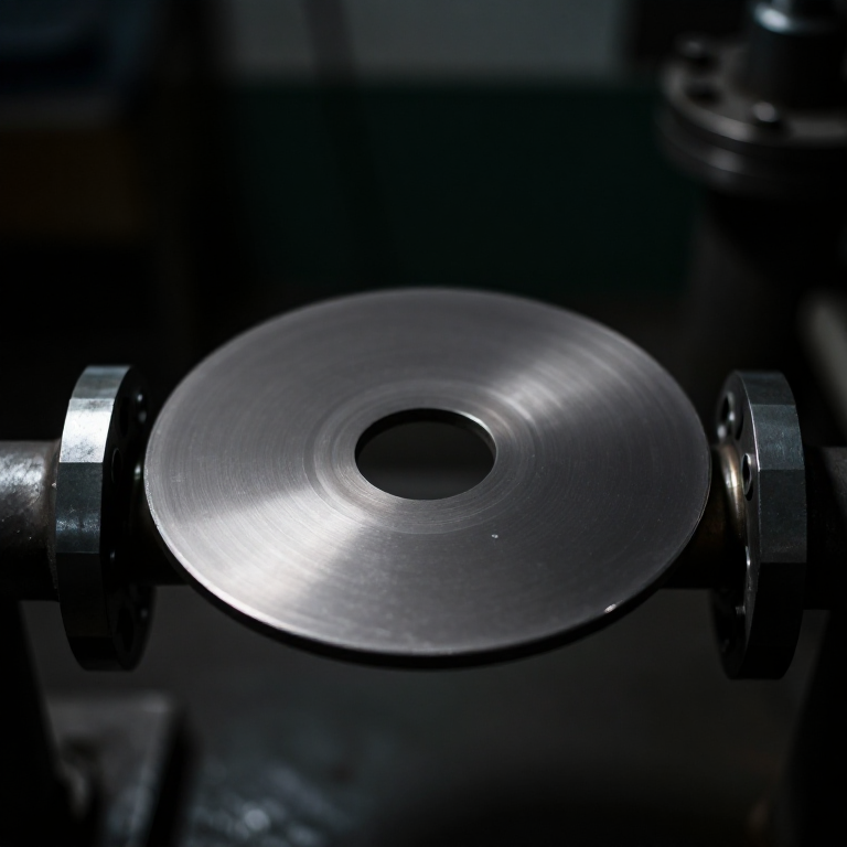


Orifice Plate Meter
手順
Cut a plate with a sharp square upstream edge
Cut a plate with a sharp square upstream edge
The edge geometry is the entire specification, and it is easy to get wrong.
- Cut a disc from 3 mm aluminium plate to fit between your pipe flanges.
- Bore a central hole of about half the pipe's internal diameter.
- Make the UPSTREAM edge perfectly square and sharp — no radius, no burr, no chamfer.
- Bevel the downstream side at 45 degrees so only a thin land remains at the bore.
- Mark the upstream face permanently.
A rounded or worn upstream edge changes the reading and cannot be seen from outside the pipe. The sharp edge makes the flow separate cleanly and form a predictable contraction just downstream; round it off and the contraction changes, the calibration shifts, and the meter quietly reads wrong for years. Erosion of that edge is the commonest cause of drift in orifice metering.
Mark the upstream face. Fitting a plate backwards is a classic and completely invisible error — the bevel then faces the flow and the meter reads substantially off.このステップの材料:
 アルミ板1 個
 アルミ平角棒1 個
必要な工具:
 コードレスドリル
 ドリルビットセット
 ヤスリセット
 糸のこ(コーピングソー)
 デジタルノギス 6インチ
 万力(ベンチバイス)
Fit tappings either side and a manometer
Fit tappings either side and a manometer
Where you take the pressure matters as much as the plate itself.
- Drill a tapping one pipe diameter UPSTREAM of the plate.
- Drill a second tapping half a pipe diameter DOWNSTREAM.
- Deburr both flush inside the pipe — a burr protruding into the flow ruins the reading.
- Connect both to a U-tube manometer filled with coloured water.
- Clamp the plate between the flanges with a gasket either side.
The downstream tap is placed at the vena contracta. The jet keeps narrowing for a short distance after the plate and reaches its smallest diameter — and lowest pressure — roughly half a pipe diameter downstream. Tapping there gives the largest, most repeatable signal. Standards specify several tapping arrangements and a meter must be built to one of them, because the calibration depends on it.
Flush, burr-free tappings. This is exactly the same requirement as the static port on the pitot tube, and for exactly the same reason.このステップの材料:
 ガラス毛細管1 個
 食用色素1 本
 外径 9.5 mm の真鍮管1 個
必要な工具:
コードレスドリルドリルビットセットヤスリセット 組み合わせスコヤデジタルノギス 6インチ
Calibrate by catching and weighing the flow
Calibrate by catching and weighing the flow
The only honest calibration is to collect what actually came out.
- Run a steady flow and record the manometer difference.
- Divert the outlet into a bucket for a timed interval.
- Weigh the water collected and compute the true flow rate.
- Repeat at five different flow rates.
- Plot flow against the square root of the pressure difference.
必要な工具:
 ストップウォッチデジタルノギス 6インチ
 デジタルキッチンスケール
Measure the permanent pressure loss and compare with the Venturi
Measure the permanent pressure loss and compare with the Venturi
This is the number that decides which meter belongs in a real plant.
- Fit a third tapping well downstream — six pipe diameters or more — where the flow has settled.
- Compare its pressure with the upstream tapping.
- That difference is energy lost forever, not just borrowed and returned.
- Express it as a percentage of the measuring differential.
- Look up or reason out the equivalent figure for a Venturi.
必要な工具:
ストップウォッチデジタルノギス 6インチコードレスドリルWhy the worse instrument won, and history
Why the worse instrument won, and history
Orifice metering was systematised in the early twentieth century, particularly by the American natural gas industry, which needed to meter enormous numbers of pipelines cheaply and consistently. The result is one of the most thoroughly standardised measurements in engineering — ISO 5167 and its relatives specify plate geometry, tapping positions, upstream straight-pipe lengths and the coefficients to use, so that any two engineers building to the standard get the same answer.
That standardisation is the real invention. The physics was understood well before; what the industry produced was an agreement precise enough that a plate cut in one country reads the same as a plate cut in another. It is the same achievement as the Whitworth thread and the Morse taper — the value is in everyone doing it identically.
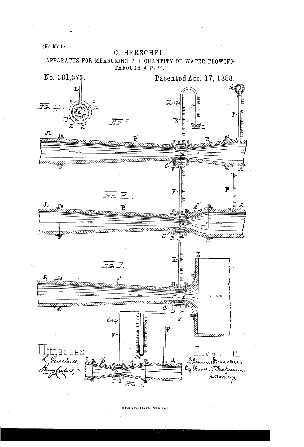
Against its sibling: the Venturi is more accurate, recovers nearly all its pressure, tolerates dirty fluid, and costs perhaps ten times as much. The orifice plate is cheap, easy to change when the process changes, and can be inspected by pulling one bolt. For a short-lived process line or one of a thousand identical gas meters, cheap and standardised beats accurate and expensive — and knowing when that is true is engineering judgement rather than physics.
Its honest limits: permanent pressure loss; a narrow useful range, since the square-law makes low flows unreadable; sensitivity to upstream disturbances, which is why standards demand long straight runs before the plate; and edge erosion that shifts the calibration invisibly over time.
材料
5- 1 個プレースホルダー
- 1 個プレースホルダー
- 1 個プレースホルダー
- 1 本プレースホルダー
- プレースホルダー
関連ブループリント
これらのブループリントは知識を共有しています — 技術、材料、原理

CC0 パブリックドメイン
このブループリントはCC0で公開されています。許可を求めずに、自由にコピー、修正、配布、あらゆる目的で使用できます。
メイカーを応援するには、ブループリント経由で製品を購入してください。メイカーには メイカーコミッション がベンダーにより設定されています。または、このブループリントの新しいイテレーションを作成し、自分のブループリントにコネクションとして含めて収益を共有できます。