コラボレーション
アート
美容とウェルネス
工芸
文化と歴史
エンターテインメント
環境
食品と飲料
リバースエンジニアリング
科学
スポーツ
テクノロジー
ウェアラブル
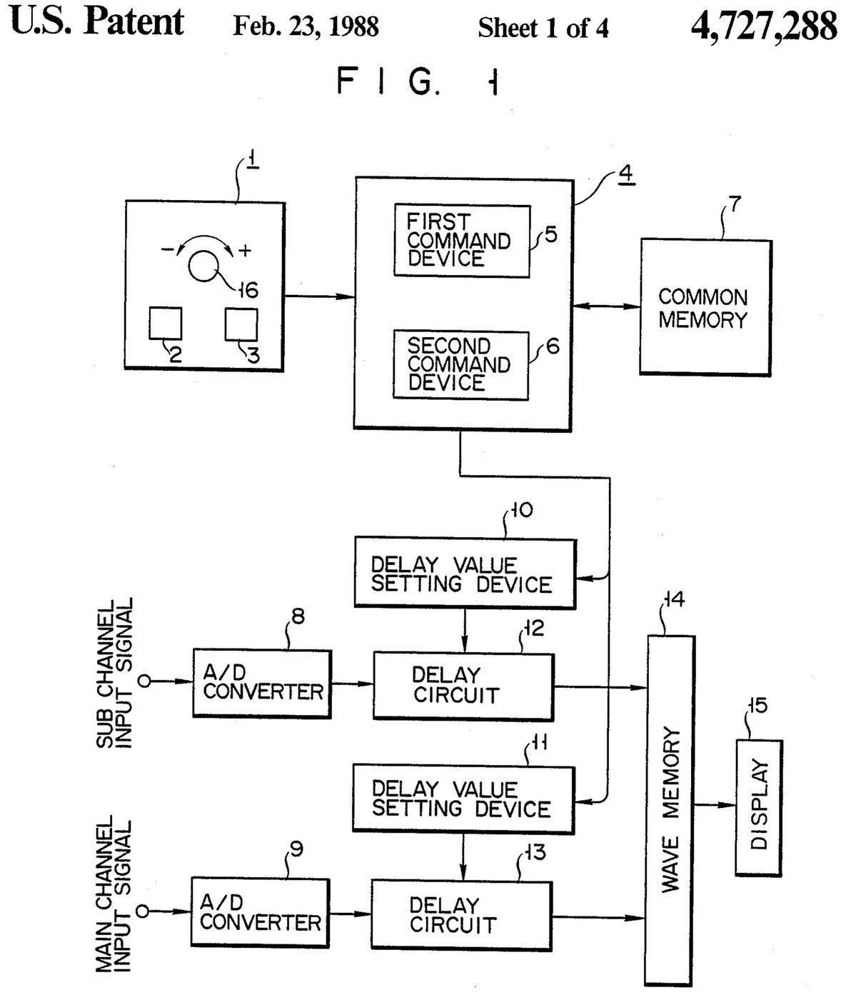


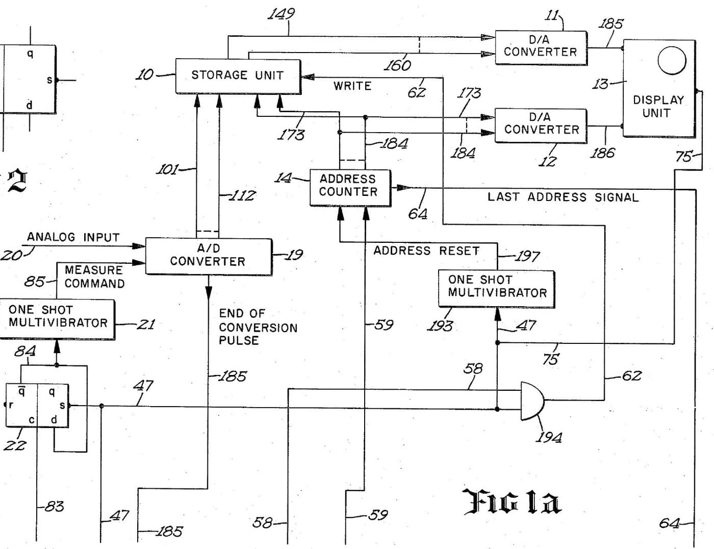
Oscilloscope: Two-Channel Digital, with a Delay per Channel and a Common Delay (Anritsu, US 4,727,288, 1988)
A two-channel digital oscilloscope. Each channel has its own converter and delay circuit. One knob, with a main and a sub button, sets the delays. The sub button shifts only the sub channel's wave, so you can line it up against the main one. The main button shifts both waves together and keeps the gap between them.
Result: a 2-channel digital oscilloscope that can move both traces along the time base without losing their phase difference.
Source: K. Nakatsugawa et al. (Anritsu), US 4,727,288 (1988). Unknown: sample rate, bandwidth, memory size and the display. Picture: the patent drawing.
エキスパート
Unknown
手順
1
1
Convert the two channels
Convert the two channels
Bring the main channel and the sub channel each to its own analog-to-digital converter. Ours: BNC sockets. Not given: the sample rate, the bandwidth.
このステップの材料:
 アナログ-デジタル変換器2 main and sub converters
 同軸コネクターセット(BNC / SO-239)1 input sockets
必要な工具:
 はんだごて
 ワイヤーストリッパー
2
2
Delay, store and display
Delay, store and display
Pass each channel's digital signal through its own delay circuit, whose delay is set by its own delay value setting device. Store both delayed signals in a wave memory and show them on the display. Ours: logic ICs for the delay circuits and setting devices, IC memory, and a CRT driven through D/A converters. Not given: how the delay circuits are built, the memory size, the display.
このステップの材料:
 ロジックICの詰め合わせ1 delay circuits and setting devices
 集積回路メモリ1 wave memory
 D/Aコンバータ2 display drive
 ブラウン管1 display
必要な工具:
はんだごてワイヤーストリッパー3
3
Build the delay panel and processor
Build the delay panel and processor
Make a delay operation panel with a main switch, a sub switch and one dial, with an encoder on the dial so each turn is read as a change in its output. Connect the panel to a microprocessor with a common memory that holds the sub channel's delay S in one area and the main channel's delay M in another. Mount it all in a case with its supply. Ours: push buttons, an aluminium case, a DC supply.
このステップの材料:
 押しボタン2 main and sub switches
 ロータリーエンコーダー1 delay dial
 マイクロプロセッサ1 command devices集積回路メモリ1 common memory
 アルミ筐体箱1 case
必要な工具:
 直流電源
 ボール盤はんだごて
4
4
Program the two commands
Program the two commands
When the dial turns, read the encoder change e and which switch is held. Sub switch: add e to S, set the sum in the sub channel's setting device and store it back as the new S. Main switch: add e to both M and S, set M + e in the main channel's device and S + e in the sub channel's, and store both back. The main command so moves both channels by the same amount and keeps their relative delay.
必要な工具:
はんだごて5
5
Compare two waves
Compare two waves
Feed two signals in. Hold the sub switch and turn the dial to slide the sub channel's wave against the main one. Then hold the main switch and turn the dial: both waves move along the time base together, with the phase difference between them unchanged. Test it with a known signal.
必要な工具:
 ファンクションジェネレータ
材料
10- 2 main and sub convertersプレースホルダー
- 1 input socketsプレースホルダー
- 1 delay circuits and setting devicesプレースホルダー
- 1 common memoryプレースホルダー
- 2 display driveプレースホルダー
- 1 displayプレースホルダー
- プレースホルダー
- プレースホルダー
- 1 command devicesプレースホルダー
- 1 caseプレースホルダー
この設計図で作るもの

関連ブループリント
これらのブループリントは知識を共有しています — 技術、材料、原理
CC0 パブリックドメイン
このブループリントはCC0で公開されています。許可を求めずに、自由にコピー、修正、配布、あらゆる目的で使用できます。
メイカーを応援するには、ブループリント経由で製品を購入してください。メイカーには メイカーコミッション がベンダーにより設定されています。または、このブループリントの新しいイテレーションを作成し、自分のブループリントにコネクションとして含めて収益を共有できます。