コラボレーション
アート
美容とウェルネス
工芸
文化と歴史
エンターテインメント
環境
食品と飲料
リバースエンジニアリング
科学
スポーツ
テクノロジー
ウェアラブル

Pocket Morse Code Learning Board - v.2
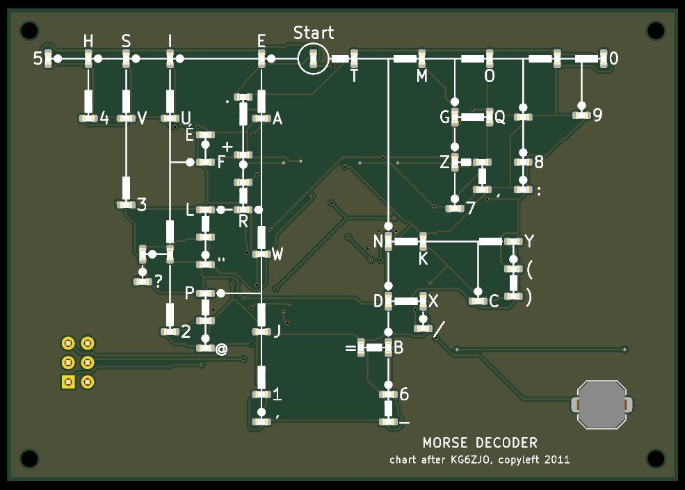
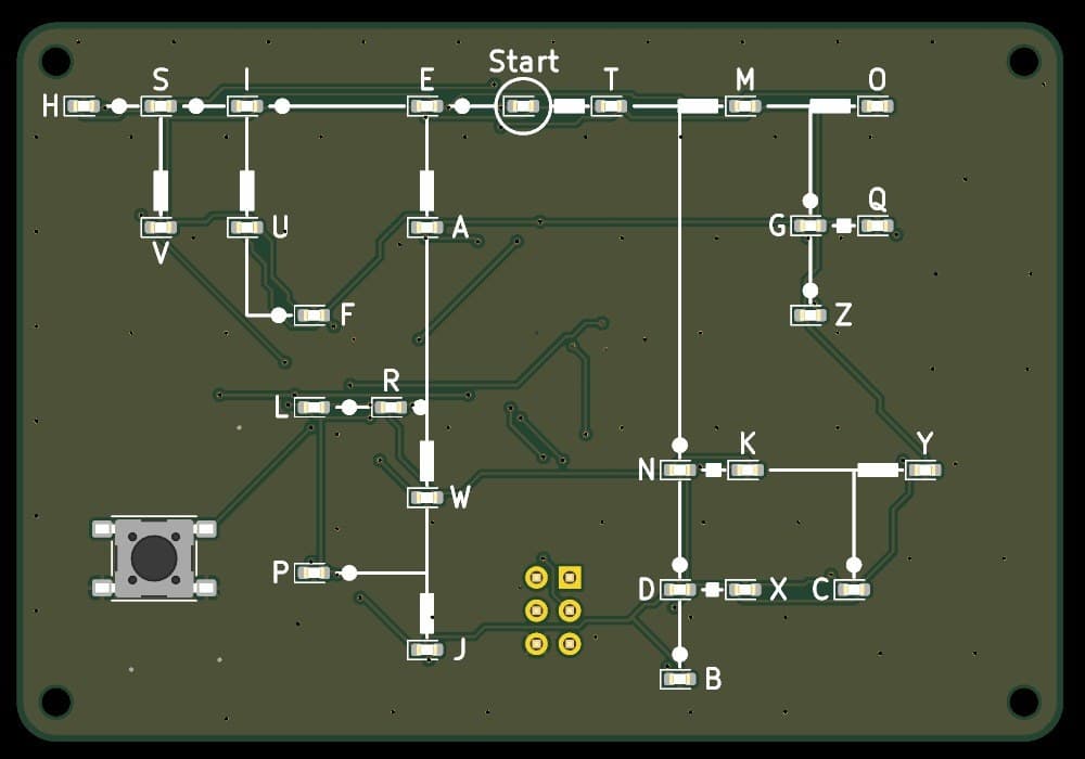
The complete pocket Morse decoder, 88 x 62 mm: every letter, the figures 0-9, the thirteen punctuation signs of the international code and the accented E, each with its own LED on Dave Nathanson's decoding chart. Press the key short for a dot and long for a dash, and the LED of the character you have reached lights; pause, and it blinks.
It runs on one CR2032 coin cell and sleeps between uses. The board was drawn with Youblob's Draw PCB, and its checks pass, but it has not been built yet.
上級者
About 1 day, plus board delivery
手順
1
1
LED current and keying speed
LED current and keying speed
Jupyter ノートブックを読み込み中…
2
2
The letters-only board, before it
The letters-only board, before it
The same design with 27 LEDs. This one adds the figures and the signs, 59 LEDs in all.
3
3
Read the chart
Read the chart
Dave Nathanson's (KG6ZJO) complete chart adds the figures to his letters: "A-Z and Numbers (I left off the punctuation & symbols for simplicity)". This board adds them back from ITU-R M.1677-1 on new branches: . , : ? ' - / ( ) " = + @ and the accented E. Eight unlabelled LEDs are waypoints on the way to a figure or sign.
4
4
The schematic
The schematic
ATmega328P on its internal 8 MHz clock, straight from the coin cell; 59 LEDs charlieplexed on nine lines (PC0-PC5, PD0, PD1, PD3) through 300 Ω resistors; the key on INT0; a 2x3 ISP footprint.
KiCanvasビューアーを読み込み中...
プロフェッショナルPCBデザインビューアー
5
5
The board
The board
Two layers, 88 x 62 mm. The chart, LEDs and key on the front; the chip, resistors, capacitors and cell holder on the back.
KiCanvasビューアーを読み込み中...
プロフェッショナルPCBデザインビューアー
6
6
Order the board
Order the board
Open the board in KiCad and plot Gerber and drill files (File > Fabrication Outputs). Order a two-layer board, 1.6 mm thick, from any board maker that takes Gerbers.
このステップの材料:
 プリント基板1 個
必要な工具:
 Arduino IDE を入れたパソコン
7
7
Solder the parts
Solder the parts
Back first: paste and reflow U1, R1-R10, C1-C3 and the cell holder BT1 with hot air. Then the front: the 59 red LEDs D1-D59 with pad 1 (cathode) as the board's assembly drawing shows, and the key SW1, a two-pad 6 x 6 mm switch to match its footprint. J1 is optional. Clean off the flux, then test each LED's direction with the meter's diode test.
このステップの材料:
 ATmega328Pマイクロコントローラ1 個
 チップLED59 個
 チップ抵抗器10 個
 セラミックチップコンデンサ3 個
 押しボタン1 個
 電池ホルダー1 個
 はんだペースト(鉛フリー)1 個
 はんだ線1 個
必要な工具:
 熱風リワークステーション
 はんだごて
 先の尖ったピンセット
 フラックス
 虫眼鏡
 マルチメーター
 イソプロピルアルコール 99 %
8
8
The firmware
The firmware
pocket_morse_decoder_complete.ino: every timing is a named constant at the top of the sketch. Board in the Arduino IDE: Arduino Pro or Pro Mini, ATmega328P (3.3V, 8 MHz).
pocket_morse_decoder_complete.inoarduino
9
9
Set the fuses and upload
Set the fuses and upload
Do not use Burn Bootloader: the Pro board setting expects a crystal, and this board has none. Hold an ISP programmer's 2x3 pins on J1 and set the internal 8 MHz clock: avrdude -c usbasp -p m328p -U lfuse:w:0xE2:m -U hfuse:w:0xD9:m -U efuse:w:0xFF:m. Then, in the Arduino IDE, use Sketch > Upload Using Programmer.
必要な工具:
 AVR ISPプログラマArduino IDE を入れたパソコン
10
10
Print the back shell
Print the back shell
An open-front tray, 92.6 x 66.6 x 8.3 mm, with four standoffs for M2 screws, a notch and floor opening to slide the cell out and an opening under J1. PLA, 0.2 mm layers, 20 % infill, printed on its floor.
11
11
Fit the shell
Fit the shell
The standoffs hold the board 6.7 mm above the floor: measure your cell holder with a cell in it before you print. Check the holder's open end faces the board's bottom edge, where the shell's cell notch is. Slide in a CR2032 and screw the board into the shell with four M2 x 8 self-tapping screws.
このステップの材料:
 PLA フィラメント1 個
 タッピンねじ4 個
 CR2032 コイン電池1 個
必要な工具:
 FDM 3D プリンター
 ノギス
 精密ドライバーセット
12
12
Troubleshooting
Troubleshooting
Pocket Morse decoder troubleshooting.
Flow
Loading...
13
13
History and honest limits
History and honest limits
The letters and figures follow **Dave Nathanson**'s (KG6ZJO) complete chart of 2011, shared as copyleft. Where the signs sit is ours; their codes are ITU-R M.1677-1's. The board, sizes, parts and timings are ours, drawn with Youblob's Draw PCB: its ERC and DRC pass with no errors and every LED's wiring, code and label was checked against the firmware by script, but it has not been built, flashed or tested.
材料
12- 1 個プレースホルダー
- プレースホルダー
- 59 個プレースホルダー
- 10 個プレースホルダー
- プレースホルダー
- プレースホルダー
- プレースホルダー
- プレースホルダー
- 1 個プレースホルダー
- 1 個プレースホルダー
- 4 個プレースホルダー
- 1 個プレースホルダー
必要な工具
12- プレースホルダー
- プレースホルダー
- 2 vendors sell this, none ship to you yetプレースホルダー
- プレースホルダー
- プレースホルダー
- プレースホルダー
- プレースホルダー
- プレースホルダー
- プレースホルダー
- プレースホルダー
- プレースホルダー
- プレースホルダー
設計ファイル
1この設計図で作るもの
関連ブループリント
これらのブループリントは知識を共有しています — 技術、材料、原理

CC0 パブリックドメイン
このブループリントはCC0で公開されています。許可を求めずに、自由にコピー、修正、配布、あらゆる目的で使用できます。
メイカーを応援するには、ブループリント経由で製品を購入してください。メイカーには メイカーコミッション がベンダーにより設定されています。または、このブループリントの新しいイテレーションを作成し、自分のブループリントにコネクションとして含めて収益を共有できます。