コラボレーション
アート
美容とウェルネス
工芸
文化と歴史
エンターテインメント
環境
食品と飲料
リバースエンジニアリング
科学
スポーツ
テクノロジー
ウェアラブル
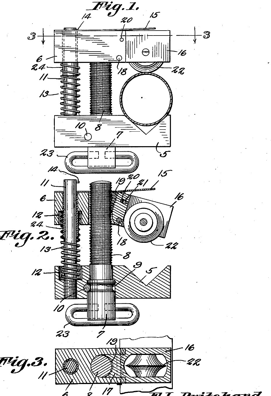


Swing-Nut Tubing Cutter: Swing the Blade Support Down and the Jaw Slides to the Tube, Up and the Screw Feeds It (Pritchard, 1941)
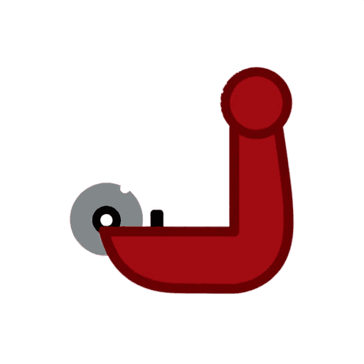
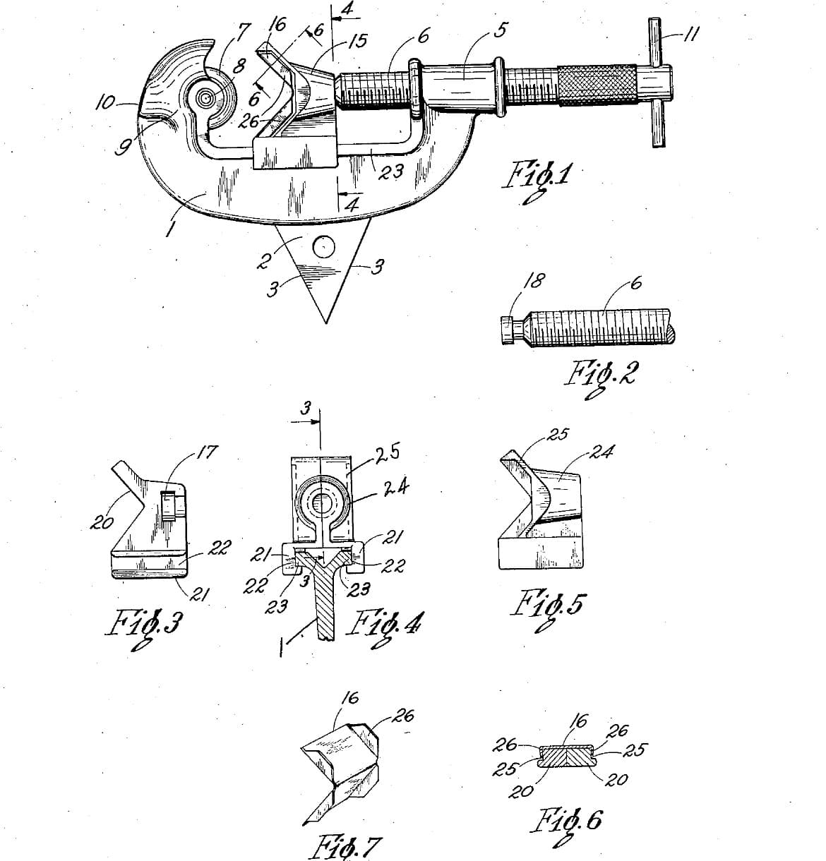
Frank L. Pritchard of Parker, Arizona, received US 2,231,593, dated 11 February 1941, for a tubing cutter small enough for a mechanic's tool box. The tube sits in a V in a fixed jaw. A movable jaw slides on the adjusting screw and a guide pin, with a spring pushing the jaws apart. The cutting wheel is held by a pivoted support with threads on its inner edge. Swung down, the support lets go of the screw, so the jaw can be pushed straight onto any tube. Swung up, it meshes with the screw again and the screw feeds the wheel in.
We make his parts from steel bar and plate. All sizes are ours.
中級者
About 3 days
手順
1
1
The swing that lets go
The swing that lets go
Jupyter ノートブックを読み込み中…
2
2
Read US 2,231,593
Read US 2,231,593
"The pivoted blade support 16 may swing downwardly until the threads thereof will be free of the threads of the screw 8. The movable jaw 6 may now be slid downwardly until the pivoted blade support is in its proper cutting position."
3
3
Print the template
Print the template
Both jaws, the blade support, the wheel and a 15 mm tube at 1:1, with the screw, pin and pivot holes. print at 100 % (check the 50 mm bar).
4
4
Make the stationary jaw
Make the stationary jaw
Saw 64 mm of 16 mm square bar, or of 16 mm plate. File the 90 degree V 8 mm deep in its top face. Drill the 6 mm pin hole and a 10 mm hole for the screw, and counterbore the pin hole 10 mm across, 5 mm deep, for the spring. Drill the 3 mm cross-pin hole across the jaw so it just cuts into the side of the screw hole.
このステップの材料:
 軟鋼板1 個
必要な工具:
 金切りのこ(ハクソー)
 ヤスリセット
 ボール盤
 マシンバイス
 ドリルビットセット
 センターポンチ
 けがき針
 万力(ベンチバイス)
 デジタルノギス 6インチ
5
5
Make the movable jaw and the support
Make the movable jaw and the support
Saw the movable jaw 50 mm long from the same bar. Drill the 6.2 mm pin hole and its spring counterbore. Saw and file a slot 8.2 mm wide down its middle, from 22 mm to the end. Saw the blade support from 14 mm plate to the template. File its upper part down to 8 mm thick, centred, so it slides into the slot, and file away its lower inner corner. Saw a 7 mm slot up its lower part for the wheel. Drill the pivot and stop-pin holes through the jaw and support together, and file the stop-pin hole in the support into a short slot.
このステップの材料:
軟鋼板1 個必要な工具:
金切りのこ(ハクソー)ヤスリセット 精密ヤスリ(針ヤスリ)セットボール盤マシンバイスドリルビットセット万力(ベンチバイス)デジタルノギス 6インチ
6
6
Tap the half nut
Tap the half nut
Pin the support in the jaw, swung up, and clamp it there. Drill 6.8 mm down the screw axis through both, so the drill cuts a shallow groove in the support's inner edge, then tap it M8 through both. Take the support out and open the jaw's own hole to 8.5 mm, so the screw passes freely and only the support's threads hold it.
必要な工具:
ボール盤マシンバイスドリルビットセット ねじ切りタップダイスセット
 切削油
7
7
Make the screw and the guide pin
Make the screw and the guide pin
Turn the top 62 mm of a 90 mm piece of 10 mm bar to 8 mm and cut an M8 thread on it with the die. Turn a groove 1.5 mm deep and 3.2 mm wide in the plain part, where the cross pin will sit, and drill a 6 mm hole across its bottom end for a T-bar. Cut the guide pin, 80 mm of 6 mm rod, and drill a 3 mm hole across its top for the stop pin.
このステップの材料:
 軟鋼丸棒1 個
 軟鋼丸棒1 個
必要な工具:
 金属旋盤
 三つ爪旋盤チャック
 旋盤の切削工具
 突切りバイトねじ切りタップダイスセットボール盤ドリルビットセット金切りのこ(ハクソー)デジタルノギス 6インチ
8
8
Turn the cutting wheel
Turn the cutting wheel
Chuck a tool steel bar and face it. Turn the end to 20 mm across for 10 mm, centre drill and drill a 5 mm hole 10 mm deep, and turn the edge to a 50 degree vee, 25 degrees each side, sharp in the middle of the 6 mm width. Part it off 6 mm long and take the burr off the hole.
このステップの材料:
 工具鋼丸棒1 個
必要な工具:
金属旋盤三つ爪旋盤チャック旋盤の切削工具突切りバイト センタードリルセットドリルビットセットデジタルノギス 6インチ
 保護めがね
9
9
Harden and temper
Harden and temper
Heat the wheel to a cherry red, until a magnet no longer sticks, and quench it in water, moving it about. Rub it bright with a stone, warm it on a piece of steel plate over the fire, and quench again as soon as it turns a light straw colour.
必要な工具:
 鍛冶炉
 鍛冶ばさみ(やっとこ)
 小さな磁石
 焼き入れ桶
 水
 砥石
 溶接用手袋保護めがね
10
10
Assemble
Assemble
Drive the guide pin into the stationary jaw. Put the screw into its hole from below and drive the cross pin in so it lies in the groove; the screw must still turn. Fit the T-bar. Slip the spring over the guide pin, then the movable jaw over the pin and the screw, and put the stop pin across the top. Fit the wheel in the support on its 5 mm pin, and pin the support into the jaw with its pivot and stop pins. Rivet a 1.5 mm steel strip along the top of the jaw, sticking out past the support as a thumb piece. Oil the threads.
このステップの材料:
 鋼製ダウエルピン5 個
 圧縮ばねセット1 個
 ばね鋼帯1 個
 鋼製リベット2 個軟鋼丸棒1 個
必要な工具:
 片手ハンマー(球頭)センターポンチ万力(ベンチバイス)ボール盤ドリルビットセット切削油
11
11
Cut a copper tube
Cut a copper tube
Mark a copper tube and hold it in a vice with soft jaws, or by hand for small tubes. Swing the support down, push the movable jaw down until the wheel touches the tube in the V, swing it up into the screw, and tighten the screw a little. Turn the cutter once round, give the screw about a quarter turn, and go on until the tube parts. The wheel should run in its own groove; the end should be square and not squeezed oval. Clean the inside of the end with a deburring tool.
このステップの材料:
 銅管1 個
必要な工具:
万力(ベンチバイス) バリ取り工具デジタルノギス 6インチ
12
12
Troubleshooting
Troubleshooting
Swing-nut tubing cutter troubleshooting.
Flow
Loading...
13
13
History and honest limits
History and honest limits
**Frank L. Pritchard** of Parker, Arizona, US 2,231,593, dated 11 February 1941, filed 17 November 1939. He claimed "a pivoted blade support mounted on the movable jaw and having threads on the inner edge thereof adapted to engage the threads of said screw". His movable jaw had a bushing for the guide pin and a looped handle on the screw head; ours has a drilled hole and a T-bar. The patent gives no sizes or materials; all of ours are ours.
材料
9- 1 個プレースホルダー
- 1 個プレースホルダー
- 1 個プレースホルダー
- 1 個プレースホルダー
- 5 個プレースホルダー
- 1 個プレースホルダー
- 1 個プレースホルダー
- 2 個プレースホルダー
- 1 個プレースホルダー
必要な工具
27- プレースホルダー
- プレースホルダー
- プレースホルダー
- プレースホルダー
- プレースホルダー
- プレースホルダー
- プレースホルダー
- プレースホルダー
- プレースホルダー
- プレースホルダー
- プレースホルダー
- プレースホルダー
- プレースホルダー
- プレースホルダー
- プレースホルダー
- プレースホルダー
- プレースホルダー
- プレースホルダー
- プレースホルダー
- プレースホルダー
- プレースホルダー
- プレースホルダー
- プレースホルダー
- プレースホルダー
- プレースホルダー
- プレースホルダー
- プレースホルダー
設計ファイル
1この設計図で作るもの
関連ブループリント
これらのブループリントは知識を共有しています — 技術、材料、原理

CC0 パブリックドメイン
このブループリントはCC0で公開されています。許可を求めずに、自由にコピー、修正、配布、あらゆる目的で使用できます。
メイカーを応援するには、ブループリント経由で製品を購入してください。メイカーには メイカーコミッション がベンダーにより設定されています。または、このブループリントの新しいイテレーションを作成し、自分のブループリントにコネクションとして含めて収益を共有できます。