コラボレーション
アート
美容とウェルネス
工芸
文化と歴史
エンターテインメント
環境
食品と飲料
リバースエンジニアリング
科学
スポーツ
テクノロジー
ウェアラブル
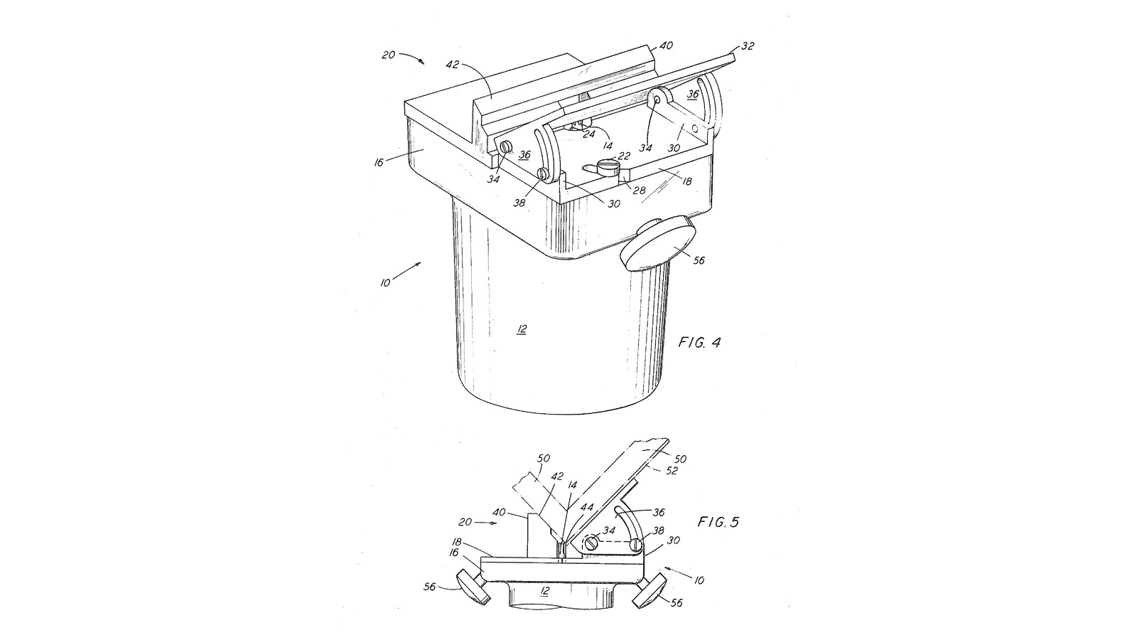


Laminate Bevel Trimmer: Two Pads at Right Angles Hold a Small Router at 45 Degrees on a Corner (Roche, 1971)
Edward Noland Roche of Cockeysville, Maryland, received US 3,628,579, dated 21 December 1971, for a small router that bevels plastic laminate in place. Laminate is usually trimmed after it is glued down, and a mitred corner meant mitring the wood underneath too. Roche's tool rides on the corner of the already-built carcass. A fixed pad with a 45 degree face sits on the top surface, a tilting pad sits on the side face, and the cutter between them bevels the laminate's edge inwards, exactly to the edge beneath it. The guide base swings slightly on a pivot to line the pad up with the cutter.
We print the motor unit, base and pads in PETG round a small DC motor. The 45 degrees is his; the other sizes are ours.
上級者
About 2 days
手順
1
1
Why the substrate needs no mitre
Why the substrate needs no mitre
Jupyter ノートブックを読み込み中…
2
2
Read US 3,628,579
Read US 3,628,579
"This pad 40 has a raised guide face 42 that slopes at a 45 degree plane which extended, coincides with the far edge of the cutting tool." "An inwardly sloping bevel 58 which exactly conforms with the edge of the substrate 50 results."
3
3
Print the motor unit
Print the motor unit
The motor unit 12: a tube for a 42 mm motor with the square faceplate 16 at its end, an 18 mm hole and two M4 holes for the motor, a hole to tap M4 for the pivot stud 26 and one to tap M5 for the adjusting screw 22, and two handle bosses. Print it faceplate down. PETG, 0.2 mm layers, 40 % infill, 5 walls.
4
4
Print the guide base
Print the guide base
The base 18: a flat plate with the clearance hole 24, the stud hole, the curved slot 28, the fixed pad 40 with its 45 degree face 42, and the two ears 30. Print it plate down. PETG, 0.2 mm layers, 40 % infill, 5 walls.
5
5
Print the adjustable pad
Print the adjustable pad
The pad 32 with its two cheeks 36, each with a hole for the pivot screw 34 and an arc slot for the locking screw 38. Print it plate down. PETG, 0.2 mm layers, 40 % infill, 5 walls.
6
6
Motor unit
Motor unit
Tap the faceplate's two holes M4 and M5. Fit the collet adapter on the motor, stand the motor in the tube with its face on the faceplate and the collet through the hole, screw it in with two M4 screws, and wire it through a toggle switch to the DC supply. Turn two hardwood knobs 56 and bolt them to the handle bosses.
このステップの材料:
 PETGフィラメント1 個
 電動機1 個
 Motor Shaft Collet Adapter1 個
 六角穴付きボルト2 個
 トグルスイッチ1 個
 配線用ワイヤー1 個
 熱収縮チューブ1 個
 堅木の板1 個
 六角ボルト詰め合わせ2 個
 六角ナット2 個
必要な工具:
 FDM 3D プリンター
 ねじ切りタップダイスセット
 タップハンドル
 直流電源
 電気はんだごて
 六角レンチセット
 木工旋盤
 コードレスドリル
 ドリルビットセット
7
7
Guide base, pads and setting
Guide base, pads and setting
Fit a 1/4 inch straight bit in the collet. Lay the base on the faceplate, the cutter through its hole; screw an M4 screw through the corner hole into the faceplate as the pivot stud 26, and an M5 screw with a washer through the curved slot as the adjusting screw 22. Hold a straightedge on the fixed pad's sloping face, reaching past the cutter, and swing the base on its stud until the straightedge just touches the cutter's far edge; tighten the adjusting screw. Hang the adjustable pad on the ears with two M4 pivot screws 34 and two M4 locking screws 38 through its arc slots; set it square to the fixed pad's face for 90 degree corners and lock it.
このステップの材料:
六角穴付きボルト6 個 平ワッシャー3 個
必要な工具:
 ルータービットセット六角レンチセット
 組み合わせスコヤ
 分度器
8
8
Bevel a laminate edge
Bevel a laminate edge
Clamp a sheet temporarily to one face of the built carcass with its edge standing proud past the corner. Hold the tool by its knobs at 45 degrees, fixed pad on the top surface and adjustable pad on the side, switch on and run it along the edge until both pads bear on the work and the cutting stops: the laminate's edge is bevelled exactly to the corner. Take the sheet off, keep it for gluing, and do the next face.
必要な工具:
 バークランプ
 保護めがね
9
9
Troubleshooting
Troubleshooting
Laminate trimmer troubleshooting.
Flow
Loading...
10
10
History and honest limits
History and honest limits
**Edward Noland Roche** of Cockeysville, Maryland, US 3,628,579, dated 21 December 1971, filed 18 November 1969. He claimed a laminate chamfering machine with a faceplate and cylindrical cutter, a guide base pivoted at one corner and locked through "a curved slot formed therein to the radius from said pivot means", pads on the base's two halves, and "a guide pad having a raised guide face sloping at a predetermined plane which extended coincides with the far edge of said cutting tool". He gives the 45 degree slope and no sizes; ours are printed PETG parts round a small DC motor, and we set the pad to the cutter with a straightedge rather than by a figure.
材料
11- 1 個プレースホルダー
- 1 個プレースホルダー
- プレースホルダー
- 8 個プレースホルダー
- プレースホルダー
- プレースホルダー
- 1 個プレースホルダー
- 1 個プレースホルダー
- 2 個プレースホルダー
- 2 個プレースホルダー
- 3 個プレースホルダー
必要な工具
14- プレースホルダー
- プレースホルダー
- プレースホルダー
- プレースホルダー
- プレースホルダー
- プレースホルダー
- プレースホルダー
- 1 vendor sell this, none ship to you yetプレースホルダー
- プレースホルダー
- 1 vendor sell this, none ship to you yetプレースホルダー
- プレースホルダー
- プレースホルダー
- プレースホルダー
- プレースホルダー
設計ファイル
3この設計図で作るもの

関連ブループリント
これらのブループリントは知識を共有しています — 技術、材料、原理
CC0 パブリックドメイン
このブループリントはCC0で公開されています。許可を求めずに、自由にコピー、修正、配布、あらゆる目的で使用できます。
メイカーを応援するには、ブループリント経由で製品を購入してください。メイカーには メイカーコミッション がベンダーにより設定されています。または、このブループリントの新しいイテレーションを作成し、自分のブループリントにコネクションとして含めて収益を共有できます。