アート
美容とウェルネス
工芸
文化と歴史
エンターテインメント
環境
食品と飲料
リバースエンジニアリング
科学
スポーツ
テクノロジー
ウェアラブル
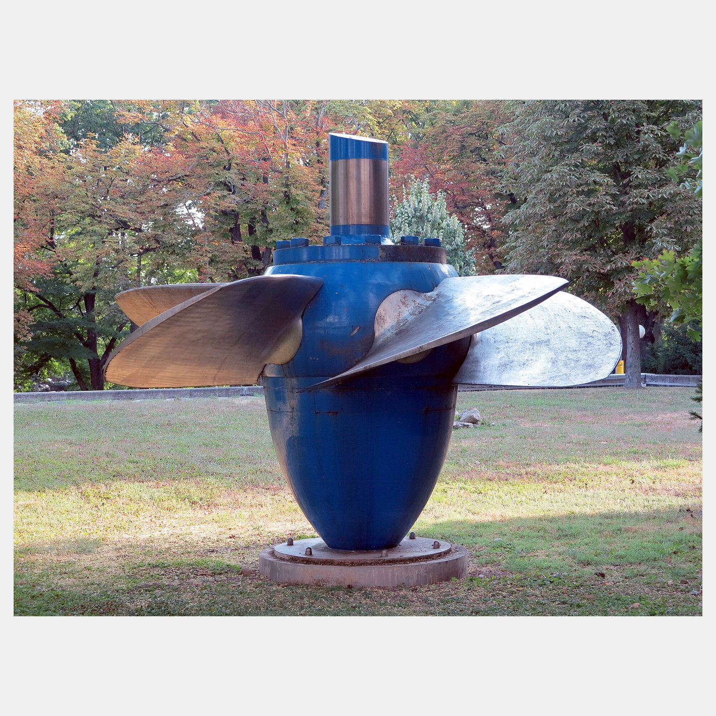


The Kaplan Turbine: A Propeller in a Pipe, With Blades That Turn
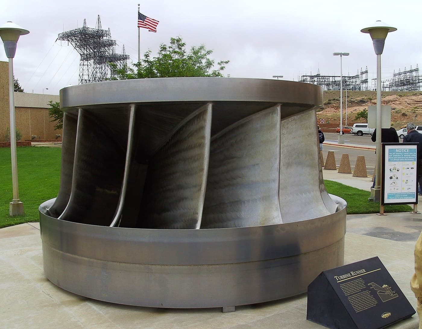
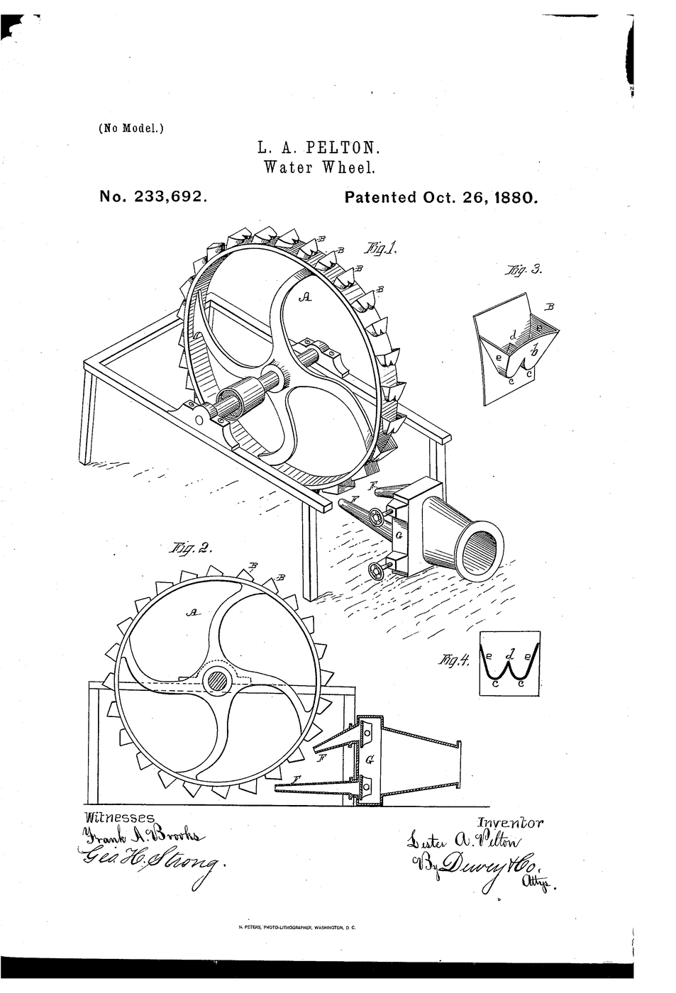
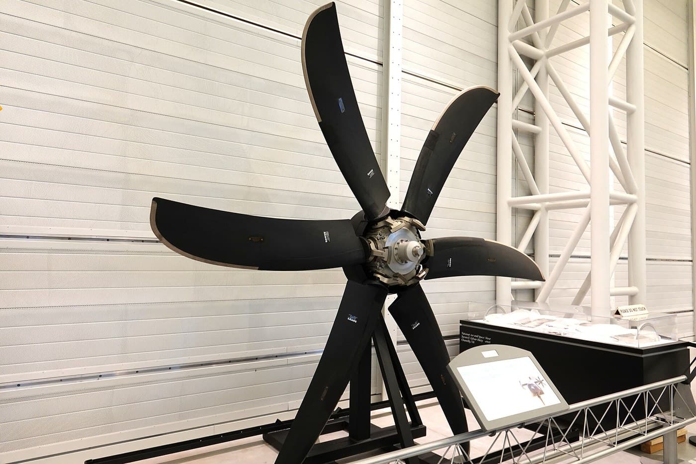
The Pelton wheel suits high heads and small flows, the Francis turbine the middle. At low heads — a river weir, a tidal barrage, a few metres of fall — the water must pass in enormous volume, and the right runner is a propeller in a pipe.
A fixed propeller only works well at one flow. Viktor Kaplan, in Brno, made the blades turn in the hub, patented in Austria from 1912–13, so that the blade angle follows the flow and the efficiency stays high as the river rises and falls. The first commercial installation ran in 1918.
This rung works out why the blades must turn, and builds a small pipe turbine whose blade pitch you can set.
中級者
About 5 hours
手順
1
1
Why the blades must turn
Why the blades must turn
Jupyter ノートブックを読み込み中…
2
2
Build a pipe turbine with settable blades
Build a pipe turbine with settable blades
Print a four-bladed runner 70 mm across whose blades are separate parts, each on a short pin in the hub, with a set screw so each blade's angle can be fixed at 15°, 25° or 35°. The runner fits inside a 75 mm PVC pipe on a shaft carried by a printed spider bearing, and drives a hobby motor used as a generator, sealed outside the pipe through an O-ring gland.
Upstream of the runner, fit a ring of fixed guide vanes printed to give the water a little swirl — the wicket gate of a real Kaplan.
このステップの材料:
 塩ビ管1 個
 塩ビ管継手セット1 セット
 PETGフィラメント120 g
 ギヤードモーター1 個
 O リングセット1 キット
 鋼の棒材1 個
 シリコーンシーラント1 個
必要な工具:
 FDM 3D プリンター
 パイプカッター
 六角レンチセット
 デジタルノギス 6インチ
3
3
Find the best blade angle at two flows
Find the best blade angle at two flows
Feed the pipe from the submersible pump in a bucket, with a ball valve to set the flow; time a measuring jug at the outlet to know the flow. Load the generator with a 330 Ω resistor and read the voltage; power is V² ÷ R.
At full flow, try each blade angle and note the power. Then close the valve to about half flow and try each again. The best angle at half flow is flatter than at full flow — exactly what a Kaplan runner's blade-turning gear does automatically.
このステップの材料:
 水20 リットル
 黄銅ボールバルブ1 個
 330 オーム抵抗1 個
必要な工具:
 水中ポンプ
 バケツ
 計量ジャグ
 ストップウォッチ
 マルチメーター
 デジタル回転計
4
4
History and context
History and context
**Viktor Kaplan**, professor at the German Technical University in Brno, patented the propeller turbine with adjustable runner blades in Austria in 1912–13; the first installation went into service in 1918. His US patent number is not asserted here — it could not be read from a primary source — and the mechanism is fully documented.
Kaplan turbines and their fixed-blade relatives run most low-head hydro plants, and the bulb turbine — a Kaplan runner with the generator in a pod inside the water passage — runs tidal barrages.
**Honest limits.** At low head the machine is large and slow for its power. Kaplan runners are prone to cavitation (the NPSH problem of the centrifugal pump rung, in reverse). And the blade-turning mechanism inside the hub must stay watertight for decades.
材料
10- 1 個プレースホルダー
- 1 セットプレースホルダー
- 120 gプレースホルダー
- プレースホルダー
- 1 キットプレースホルダー
- 1 個プレースホルダー
- 1 個プレースホルダー
- 20 リットルプレースホルダー
- 1 個プレースホルダー
- 1 個プレースホルダー
関連ブループリント
これらのブループリントは知識を共有しています — 技術、材料、原理

CC0 パブリックドメイン
このブループリントはCC0で公開されています。許可を求めずに、自由にコピー、修正、配布、あらゆる目的で使用できます。
メイカーを応援するには、ブループリント経由で製品を購入してください。メイカーには メイカーコミッション がベンダーにより設定されています。または、このブループリントの新しいイテレーションを作成し、自分のブループリントにコネクションとして含めて収益を共有できます。