アート
美容とウェルネス
工芸
文化と歴史
エンターテインメント
環境
食品と飲料
リバースエンジニアリング
科学
スポーツ
テクノロジー
ウェアラブル


The Peristaltic Pump: Two Places Closed at Once, and No Valve Touches the Fluid
Squeeze a hose shut between two fingers and slide them along it: the liquid ahead is pushed forward, and the hose springs back behind your fingers and fills again. That is the whole of a peristaltic pump. A rotor carries rollers round a curved track, each pinching a flexible tube shut and rolling along it.
Nothing but the inside of the tube ever touches the liquid. There are no valves to clog, no seals to leak and nothing to clean except a tube that can be thrown away. That is why this is the pump for blood, for cell cultures, for dosing chemicals into a water supply, for concrete and for printer ink.
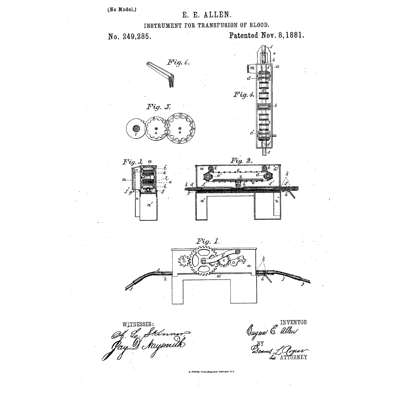
Rufus Porter and J. D. Bradley patented it in 1855 as a well pump, and wrote down the one rule every peristaltic pump still has to obey: the tube must be closed at **two places at the same instant**. In 1881 Eugene Allen used the same principle to move blood, precisely because it has no valves for blood to clot on. This rung builds one on a stepper motor.
中級者
About 6 hours
手順
1
1
Choose the tube first — it sets everything else
Choose the tube first — it sets everything else
The tube is the pump. Its bore decides the flow per turn, its wall decides how hard the rollers must squeeze, and its material decides what it can carry and how long it lasts.
Use **silicone** tubing for this build: it recovers its round shape quickly after each pinch, which is what refills the pocket behind the roller. Clear PVC tubing is cheaper and stiffer — it recovers more slowly, takes a permanent flat set sooner and suits only slow, occasional duty.
Measure the inside diameter and the wall thickness with calipers, on a cut end, at several points round the circle. A tube squeezed flat is exactly **two walls thick**; that is the starting gap between roller and track. Write both numbers down — the track is designed around them in the next step.
このステップの材料:
 シリコンチューブ1 メートル
必要な工具:
 デジタルノギス 6インチ
2
2
Print the track, the rotor and the rollers
Print the track, the rotor and the rollers
Print a housing with a curved track of 25 mm radius to the tube's centreline, wrapping **at least 180 degrees** — a U-shape with the tube entering on one leg and leaving on the other. Print a three-arm rotor that fits the stepper motor's 5 mm shaft with a grub screw, and fit a skateboard bearing on a machine screw at the end of each arm as a roller. Rolling bearings instead of fixed pegs is the difference between a pump and a tube cutter: a peg drags along the tube and wears through it.
Make the track a separate part held by two screws in slotted holes, so you can move it towards the rotor. That adjustment is the **occlusion** — how hard the tube is squeezed — and it is the only setting the pump has.
Clamp the tube at both ends of the track with printed clips, or it will creep round with the rollers until it is pulled tight and stops pumping.
このステップの材料:
 PETGフィラメント120 g
 ボールベアリング3 個
 小ねじ10 個
 ステッピングモーター1 個
必要な工具:
 FDM 3D プリンターデジタルノギス 6インチ
 六角レンチセット
 コードレスドリル
 ドリルビットセット
3
3
Flow per turn, and the two-closed-places rule
Flow per turn, and the two-closed-places rule
Jupyter ノートブックを読み込み中…
4
4
The drive: a stepper, a speed knob and a reverse button
The drive: a stepper, a speed knob and a reverse button
A stepper motor is the right drive for a dosing pump: it turns a known angle per step, so the volume pumped is simply steps counted. This sketch reads a potentiometer for speed and a button to reverse — reversing is how you clear an air lock or empty a line back into its bottle. Set the driver's current limit before connecting the motor; a stepper run at the wrong current either stalls under the tube's resistance or overheats.
peristaltic_drive.inoarduino
このステップの材料:
 Arduino Uno R31 個
 ステッピングモータードライバー1 個
 可変抵抗器1 個
 ジャンパワイヤ1 セット
必要な工具:
 Arduino IDE を入れたパソコン
 直流電源
直流電源5
5
Set the occlusion and calibrate against a column of water
Set the occlusion and calibrate against a column of water
Start with the track backed off so the rollers barely touch the tube. Put the inlet in a beaker of water with a drop of dye, lead the outlet into a graduated cylinder and run the pump slowly.
Move the track in a little at a time. At first the pump delivers almost nothing: the rollers push the liquid forward and it slips back past them. When the gap reaches about twice the wall thickness the flow jumps. Now raise the outlet a metre above the inlet and watch the dye: if it creeps backward between roller passes, close the track a little more. Stop as soon as it holds.
Do not go further than that. Every extra fraction of a millimetre crushes the tube on every pass and shortens its life, and gives no more flow.
Now calibrate: count 100 turns into the cylinder, divide, and compare with the notebook's figure. The real pump delivers less, because the tube does not fully recover its round shape between rollers. That measured number, not the calculated one, is what a dosing pump runs on.
このステップの材料:
 水1 リットル
 食用色素(流れを見るための染料)1 滴
必要な工具:
 メスシリンダー
 ストップウォッチ六角レンチセット
 メジャー(巻尺)
6
6
Pulses and tube wear
Pulses and tube wear
Jupyter ノートブックを読み込み中…
7
7
The flow has drifted: find out why
The flow has drifted: find out why
A peristaltic pump's flow is only as good as its tube and its occlusion. These are the faults that change the calibrated millilitres per turn, in the order to check them.
Flow
Loading...
8
8
History and context
History and context
**US 12,753, 'Elastic-Tube Pump', Rufus Porter of Washington DC and J. D. Bradley of Brattleboro, Vermont, dated 17 April 1855.** Porter was the founder of Scientific American. The patent describes vulcanized india-rubber hose — only commercially available for a decade at that point — fixed round a cylindrical surface and traversed by a roller, and it names the condition that makes the pump work: the hose must be *"closed at the same instant"* in two places. One way they gave of doing it was to coil the hose a whole turn.
**US 249,285, 'Instrument for Transfusion of Blood', Eugene E. Allen of Grand Rapids, Michigan, filed 23 June 1881, granted 8 November 1881.** A rubber hose about an eighth of an inch in bore laid on a rubber cushion in a small brass box, with three or more glass rollers carried on an endless belt so that one always pressed it shut. Allen's specification says why: the moving pressure *"dispens[es] with all suction-valves, which, on account of the sticky and fibrinous nature of blood, will always clog and produce clots"*.
The roller pump went on to move blood in heart-lung and dialysis machines for the same reason Allen gave.
**Honest limits.** It pulses. Its flow depends on a tube that wears, so it drifts and must be re-calibrated. It is limited in pressure by what the tube can seal against — a few bar for ordinary laboratory tubing. And a worn tube does not fail gracefully: it splits, and whatever it was carrying ends up in the pump head.
材料
11- 1 メートルプレースホルダー
- 120 gプレースホルダー
- プレースホルダー
- 10 個プレースホルダー
- プレースホルダー
- プレースホルダー
- プレースホルダー
- プレースホルダー
- プレースホルダー
- 1 リットルプレースホルダー
- プレースホルダー
関連ブループリント
これらのブループリントは知識を共有しています — 技術、材料、原理
Building Ctesibius' Force Pump — The First Double-Acting Piston Pump
Emma 作
力学
150
0
0
0
3
0
One Way Only: The Check Valve and the Bang It Makes
Martin 作
工具
39
0
0
0
0
0
Vulcanizing Rubber with Sulfur — The Accidental Discovery That Put Tyres on the Road
Charlie 作
産業用
113
0
0
0
3
0
The Hose and Its Clip: Why It Was Tight When You Fitted It
Martin 作
工具
38
0
0
0
0
0
The Plastic Blood Bag
Mary 作
医学
46
0
0
0
0
0
The Centrifugal Pump: Speed Squared, and Why It Cannot Lift Air
Emma 作
力学
34
0
0
0
0
0
CC0 パブリックドメイン
このブループリントはCC0で公開されています。許可を求めずに、自由にコピー、修正、配布、あらゆる目的で使用できます。
メイカーを応援するには、ブループリント経由で製品を購入してください。メイカーには メイカーコミッション がベンダーにより設定されています。または、このブループリントの新しいイテレーションを作成し、自分のブループリントにコネクションとして含めて収益を共有できます。