コラボレーション
アート
美容とウェルネス
工芸
文化と歴史
エンターテインメント
環境
食品と飲料
リバースエンジニアリング
科学
スポーツ
テクノロジー
ウェアラブル
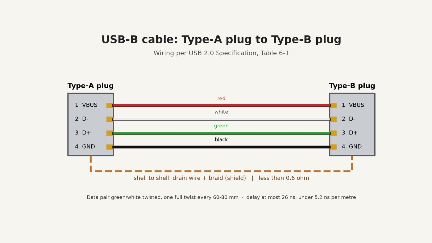


USB-B Cable: Type-A Plug to Type-B Plug, Wired to the USB 2.0 Specification
A USB-B cable joins a computer (Type-A plug) to a device such as an Arduino board or a printer (Type-B plug).
The USB 2.0 Specification (USB Implementers Forum, 2000) fixes the wiring: contact 1 VBUS on the red wire, 2 D- white, 3 D+ green, 4 GND black, and the plug shells joined through the cable's shield. It also sets the cable's build and its limits: a twisted green-white data pair, a red-black power pair, foil and braid shields, no more than 26 ns of delay, and less than 0.6 ohm from shell to shell.
This rung works out how long the cable may be, then cuts a 1.5 m shielded cable, solders a Type-A plug to one end and a Type-B plug to the other, and checks every wire with a multimeter.
Source: Universal Serial Bus Specification Rev. 2.0, sections 6.4.1, 6.5.2, 6.6, 7.1.16, 7.2.2. Picture: our own drawing.
中級者
About 1 hour
手順
1
1
How long may it be?
How long may it be?
The delay and voltage-drop limits from the specification, and what they allow for each wire size.
2
2
Cut and strip the cable
Cut and strip the cable
Cut 1.5 m of shielded USB cable with a 24 AWG power pair. At each end, slit and remove 20 mm of the PVC jacket with the knife. Comb the braid back over the jacket, trim the foil off and keep the bare drain wire. Strip 3 mm of insulation from the red, black, green and white wires.
このステップの材料:
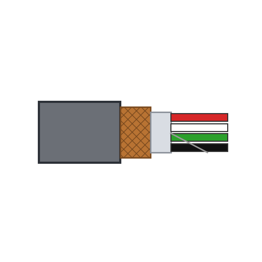 シールド付きUSBケーブル1.5 m
必要な工具:
 メジャー(巻尺)
 カッターナイフ
 ニッパー
 ワイヤーストリッパー
 保護めがね
3
3
Solder the Type-A plug
Solder the Type-A plug
Slide the plug's hood and a 40 mm piece of heat-shrink tubing onto the cable. Tin the wires and solder them to the plug's contacts: 1 red (VBUS), 2 white (D-), 3 green (D+), 4 black (GND). Twist the drain wire into the braid and solder both to the plug's metal shell.
このステップの材料:
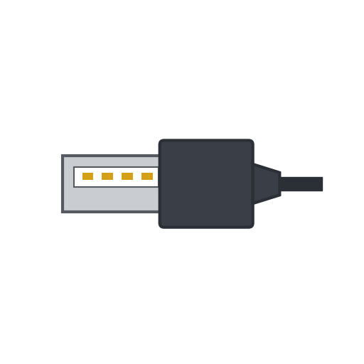 USBタイプAプラグ1 個
 熱収縮チューブ40 mm
 はんだ線1 as required
必要な工具:
 はんだごて
 ヘルピングハンド
4
4
Solder the Type-B plug
Solder the Type-B plug
Do the same at the other end with the Type-B plug: 1 red (VBUS), 2 white (D-), 3 green (D+), 4 black (GND), drain wire and braid to the shell. Pin 1 must reach pin 1 at both ends.
このステップの材料:
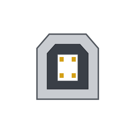 USBタイプBプラグ1 個熱収縮チューブ40 mmはんだ線1 as required
必要な工具:
はんだごてヘルピングハンド5
5
Check every wire
Check every wire
With the multimeter, check that each contact connects to the same contact at the other end and to no other, and that no contact touches a shell. Measure from shell to shell: the specification asks for less than 0.6 ohm.
必要な工具:
 マルチメーター
6
6
Close the plugs
Close the plugs
Clip the hoods over the plugs, slide the heat-shrink tubing over each joint between hood and cable, and shrink it with the heat gun as a strain relief.
必要な工具:
 ヒートガン
7
7
History and honest limits
History and honest limits
The specification's revision history dates USB 1.0 to 15 January 1996, 1.1 to 23 September 1998 and 2.0, which added high speed, to 27 April 2000.
The specification requires a standard detachable cable to end in OVERMOLDED plugs; ours has hand-soldered plugs in hoods, so it is not a compliant cable. We do not measure its 90 ohm impedance or its delay. The 1.5 m length, the 24 AWG power pair and the strip lengths are ours. How the plugs and the cable are made is not covered (unknown heads).
材料
5- 1.5 mプレースホルダー
- 1 個プレースホルダー
- 80 mmプレースホルダー
- 2 as requiredプレースホルダー
- 1 個プレースホルダー
この設計図で作るもの

CC0 パブリックドメイン
このブループリントはCC0で公開されています。許可を求めずに、自由にコピー、修正、配布、あらゆる目的で使用できます。
メイカーを応援するには、ブループリント経由で製品を購入してください。メイカーには メイカーコミッション がベンダーにより設定されています。または、このブループリントの新しいイテレーションを作成し、自分のブループリントにコネクションとして含めて収益を共有できます。