SANAA
UREMBO NA USTAWI
UJANJA
UTAMADUNI NA HISTORIA
BURUDANI
MAZINGIRA
CHAKULA NA VINYWAJI
BAADAYE YA KIJANI
REVERSE ENGINEERING
SAYANSI
MICHEZO
TEKNOLOJIA
VAZI
Limetafsiriwa
BLUEPRINT NFT

Kuangaza LED — Mradi Wako wa Kwanza wa Arduino
Mradi wa kawaida wa kwanza wa elektroniki! Jenga mzunguko wa kuangaza LED kwa kutumia Arduino, breadboard, resistor, na LED moja. Kamili kwa wanaoanza kabisa — hakuna kuzibua kwa moto kinachohitajika.
Maagizo
1
1
Kukua Sehemu Zako
Kukua Sehemu Zako
Kusanya sehemu zote zilizoorodheshwa hapa chini. Hakuna haja ya kunyambua — kila kitu kinaunganisha kwenye ubao wa mkate.
Vifaa kwa hatua hii:
 SparkFun Inventor's Kit - V3.21 kifaa
Arduino Uno R31 kipande
5mm LED (any color)1 kipande
 220 ohm Resistor (1/4W)1 kipande
Breadboard1 kipande
Jumper Wires (Male-to-Male)2 vipande
USB-B Cable1 kipande
Zana zinazohitajika:
Computer with Arduino IDE
2
2
Mchoro wa Saketi
Mchoro wa Saketi
Ishara inatoka Arduino Pin 13 → resistor 220Ω (R1) → LED (D1) → GND. Resistor huzuia sasa ili kulinda LED.
Vifaa kwa hatua hii:
Arduino Uno R31 kipande
5mm LED (any color)1 kipande
220 ohm Resistor (1/4W)1 kipande3
3
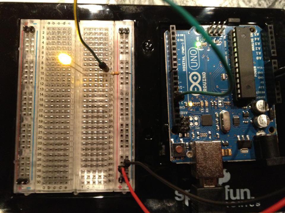
Unganisha Waya
Unganisha Waya
- Ingiza LED kwenye breadboard — mguu mrefu (anode +) katika safu moja, mguu mfupi (cathode −) katika safu inayofuata.
- Ingiza mguu mmoja wa 220Ω resistor katika safu ile ile na LED cathode. Mguu mwingine katika safu tofauti.
- Jumper wire kutoka LED anode row → Arduino Pin 13.
- Jumper wire kutoka resistor free row → Arduino GND.
Vifaa kwa hatua hii:
5mm LED (any color)1 kipande
220 ohm Resistor (1/4W)1 kipandeBreadboard1 kipande
Jumper Wires (Male-to-Male)2 vipande
4
4
Pakia Msimbo wa Blink
Pakia Msimbo wa Blink
Unganisha Arduino kupitia USB. Fungua Arduino IDE, chagua Tools → Board → Arduino Uno, bandika msimbo, na ubofye Upload.
blink.inoarduino
Vifaa kwa hatua hii:
Arduino Uno R31 kipande
USB-B Cable1 kipande
Zana zinazohitajika:
Computer with Arduino IDE
5
5
PCB Muundo (Marejeleo)
PCB Muundo (Marejeleo)
Hii inaonyesha mzunguko kama muundo wa PCB. Sio muhimu kwa mradi huu — breadboard inafanya kazi vizuri — lakini inaonyesha jinsi mzunguko sawa ungekavyoonekana kama ubao halisi uliofanywa.
6
6
Jaribu na Jaribio
Jaribu na Jaribio
LED inakiniga? Hongera! Umebainisha tu hardware.
Kutatua Matatizo:
Majaribio yajayo:
Kutatua Matatizo:
- LED haisemi? Geuka LED — mguu mrefu kuelekea Pin 13.
- LED inabaki kuwaka? Angalia nambari iliyoingizwa kwa mafanikio.
- Hakuna kinachotokea? Thibitisha wiring inafanana na mpango katika Hatua 2.
Majaribio yajayo:
- Badilisha
delay()thamani kudhibiti kasi ya kiniga - Ongeza LED ya pili kwenye Pin 12
- Badilisha na RGB LED (tazama SIK Circuit 3)
Vifaa
7- $105.00
- Kishikilia Nafasi
Jumla inayokadiriwa
$105.00Related blueprints
Other builds that share materials, tools, or techniques with this one.

Using a Shift Register — SIK Circuit 14electronics/active
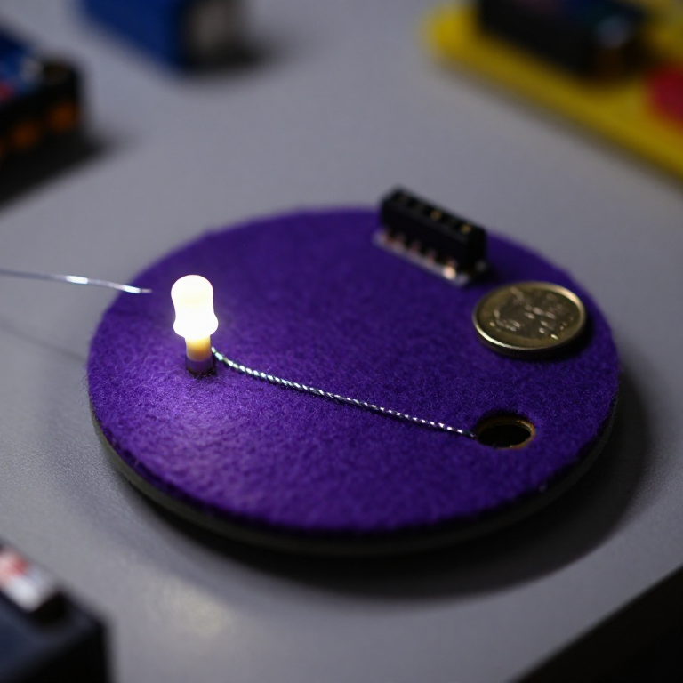
Blinking an LED with LilyPad Arduinoelectronics

Making Charcoal — The First Chemical Processmaterials
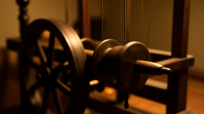
The Spinning Jenny — Multi-Spindle Yarn Productiontextiles
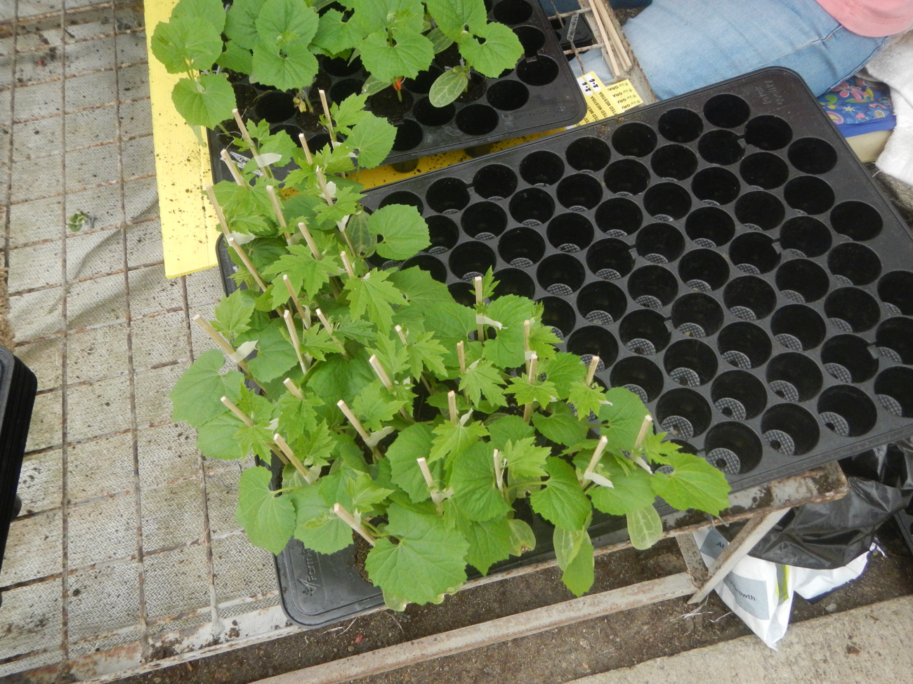
Starting Seeds Indoors — Raising Seedlings for a Head Start
Driving a Motor — SIK Circuit 12electronics/electromech
CC0 Umma Wote
Mchoro huu umetolewa chini ya CC0. Uko huru kunakili, kubadilisha, kusambaza, na kutumia kazi hii kwa madhumuni yoyote, bila kuomba ruhusa.
Saidia Mtengenezaji kwa kununua bidhaa kupitia Mchoro wao ambapo wanapata Kamisheni ya Mtengenezaji iliyowekwa na Wachuuzi, au unda marudio mapya ya Mchoro huu na uiunganishe kama kiungo katika Mchoro wako kuchangia mapato.