SANAA
UREMBO NA USTAWI
UJANJA
UTAMADUNI NA HISTORIA
BURUDANI
MAZINGIRA
CHAKULA NA VINYWAJI
UHANDISI WA KINYUME
SAYANSI
MICHEZO
TEKNOLOJIA
VAZI
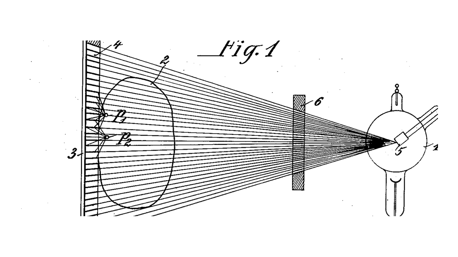


Bucky Anti-Scatter Grid
The first radiographs were foggy and nobody could say why. The beam went through the patient and onto the plate, so the picture should have been a clean shadow - but the thicker the part being photographed, the greyer and more washed-out the result, until an abdomen was barely readable at all.
The cause is that a body does not simply absorb X-rays or pass them. It **scatters** them. A photon can strike an atom, change direction, and continue on to the plate carrying no information about where it came from. Every one of those is a grey dot in the wrong place, and in a thick body they outnumber the photons that travelled straight.
Gustav Bucky's answer, in **US 1,164,987** "Method of and Apparatus for Projecting Röntgen Images" - filed 3. February 1914, granted 21. December 1915 - is beautifully simple. You cannot tell a scattered photon from a straight one by looking at it. But you CAN tell them apart by the direction they arrive from, because the straight ones all come from one point: the tube.
So he put a grid in front of the plate: "a number of chambers having walls of a form to obstruct passage of secondary Rontgen rays", with the walls parallel to the primary beam and intersecting at the anticathode. Anything travelling toward the plate from the focal spot passes down a chamber and through. Anything arriving at an angle hits a wall and stops.
**You will build this with light, and it works identically.** Scatter is simply light arriving from the wrong direction, and a grid that passes light from one point while blocking light from everywhere else is the same device. You will build a focused grid, measure its acceptance angle, and find out for yourself how brutally a focused grid punishes being at the wrong distance - the fault that still ruins radiographs today.
One thing the grid cannot do is hide itself: a stationary grid always prints its own strips across the picture. Hollis Potter's answer in 1920 was to move it during the exposure so the lines blur away, and the combination has been called the Potter-Bucky diaphragm ever since.
Mwanzo
90 minutes
Maagizo
1
1
Decide the ratio before you cut anything
Decide the ratio before you cut anything
A grid is specified by one number: the **grid ratio**, which is the height of the strips divided by the width of the gap between them. Everything else follows from it - how much scatter it removes, how narrow its acceptance angle is, and how much extra exposure it costs.
Build an 8:1 grid: strips 8 mm tall with 1 mm gaps. At that size you can cut it by hand and still measure the effect clearly, and the geometry is identical to a clinical grid ten times finer.
You need 21 strips of 8 x 120 mm card or thin aluminium, and 20 spacers 1 mm thick. Corrugated card, foam board and lolly sticks all work; what matters is that the strips are opaque to your source and the spacers are consistent.
Run the numbers in the notebook step first. An 8:1 grid accepts about 7 degrees at this scale, which is wide enough to be forgiving; a clinical 8:1 grid with 0.3 mm gaps accepts about 2 degrees, which is not.
Vifaa kwa hatua hii:
 Mabamba ya Kadibodi Yenye Mikunjo2 karatasi
 Bamba la alumini1 karatasi
Zana zinazohitajika:
 Kisu cha kazi za mikono
 Rula
Rula Mkeka wa kukatia unaojiziba
 Kipima-unene cha dijitali cha inchi 6
2
2
Build it PARALLEL first, and see the problem
Build it PARALLEL first, and see the problem
Glue the strips upright between two rails with a 1 mm spacer between each, all perfectly parallel, and let it set. Check with a caliper as you go: an error that accumulates across twenty gaps is an error you will measure later and blame on physics.
Now hold it up to a lamp about half a metre away and look through it from directly in front. The middle is clear. Move your eye to the side, or look at the outer edges, and the strips close up on you - because the light out there is arriving at an angle the parallel channels do not accept.
That is **grid cut-off**, and on a parallel grid it happens at the edges of every exposure. Bucky's patent has the fix in it: make the walls converge on the tube instead of running parallel, so that every channel points at the source. Fig. 1 of the patent - the drawing on this blueprint - shows exactly that fan.
Keep the parallel grid. Comparing the two is the measurement in step 4.
Vifaa kwa hatua hii:
Mabamba ya Kadibodi Yenye Mikunjo2 karatasi Gundi ya mbao ya PVA30 ml
 Kigingi cha mbao2 vipande
Zana zinazohitajika:
Kisu cha kazi za mikonoRula Kibanio cha springiKipima-unene cha dijitali cha inchi 6
3
3
Build the focused one: every channel aims at the same point
Build the focused one: every channel aims at the same point
Pick a focal distance and commit to it - 500 mm is convenient. Every strip must tilt so that, if you extended it, it would pass through a point 500 mm above the centre of the grid.
Draw it full size rather than calculating it. On a large sheet, mark the focus, mark the grid line 500 mm below it, and rule a line from the focus to each strip position along that grid line. Those ruled lines ARE the strip angles: build a jig by cutting slots along the drawing, and stand each strip in its own slot.
The centre strip is vertical. The outermost strip on a 120 mm grid at 500 mm focus leans by about 7 degrees. Every strip in between leans by its own amount, and getting that progression right is the whole craft of the thing.
Write the focal distance on the grid in large letters. Every real grid is marked this way, and for exactly the reason step 4 is about to demonstrate.
Vifaa kwa hatua hii:
Mabamba ya Kadibodi Yenye Mikunjo3 karatasiGundi ya mbao ya PVA30 ml Karatasi2 karatasi
Zana zinazohitajika:
Kisu cha kazi za mikonoRula Kipima-pembeMkeka wa kukatia unaojizibaKibanio cha springi
4
4
Measure the acceptance angle, and the punishment for standing wrong
Measure the acceptance angle, and the punishment for standing wrong
**Acceptance angle.** Put a small bright lamp at the focal distance, directly above the grid centre, and a light meter directly beneath. Note the reading. Now swing the LAMP around the grid centre in five-degree steps, keeping the distance the same, and read the meter at each. Plot it: the curve falls off a cliff at the angle the notebook predicted from your ratio. That cliff is what stops scatter.
**The distance penalty.** Put the lamp back on axis and now vary only its distance - 300, 400, 500, 700, 1000 mm. Read the meter at the CENTRE of the grid and again near the EDGE each time.
The centre barely changes. The edge collapses as soon as you leave the focal distance, and it collapses on both sides at once. That is the single most common error with a focused grid: the image goes dark at both edges, the operator reads it as underexposure, turns the power up, and gets the same dark edges with twice the dose.
**And the scatter test itself.** Put a scattering object - a tub of water, a block of candle wax - between lamp and grid, with a coin taped underneath as the "bone". Photograph the shadow with and without the grid. The grid version should be darker overall and have a visibly sharper washer edge. That is the trade in one picture: less signal, much less fog.
Vifaa kwa hatua hii:
 Washa bapa1 kipande
Zana zinazohitajika:
 Kipima mwanga (mwanga ulioingia/ulioakisiwa)Kipima-pembeRula
 Tripodi (nyuzi za kaboni, kichwa cha mpira)
 Tochi ya LED ya ukaguzi
5
5
Ratio, dose and focal distance in numbers
Ratio, dose and focal distance in numbers
Inapakia daftari la Jupyter…
6
6
When the grid makes it worse
When the grid makes it worse
Four questions, and the first two are the same fault seen from different sides. Each is answerable by looking at the picture.
Flow
Loading...
Zana zinazohitajika:
Kipima mwanga (mwanga ulioingia/ulioakisiwa)7
7
Compendium: Potter's fix, and why grids are disappearing
Compendium: Potter's fix, and why grids are disappearing
**The lines.** A stationary grid prints its own strips onto the image - and at 40 to 60 strips per centimetre they are fine enough to alias against a digital detector and produce moiré patterns far coarser and uglier than the strips themselves. Hollis Potter's answer in 1920 was to move the grid sideways during the exposure so the lines smear into a uniform grey. It works completely, it costs a motor and a mechanism, and the combination has been the Potter-Bucky diaphragm ever since. Potter also simplified Bucky's crossed honeycomb into parallel strips in one direction only, which absorbed nearly as much scatter and was far easier to manufacture.
**Crossed versus linear.** Bucky's original is a crossed grid - a honeycomb, catching scatter from every direction. A linear grid only catches scatter across the strips, not along them. The crossed grid is better and cannot be angled or moved, so almost everything clinical is linear.
**Interspace material.** The gaps must be filled with something rigid and as transparent to X-rays as possible. Aluminium was standard, carbon fibre is better and now usual. The strips themselves are lead: nothing else stops enough in a 0.05 mm thickness.
**Why they are going away.** The air gap technique - simply moving the patient further from the detector - lets most scatter miss the detector entirely, with no grid and no dose penalty. And modern software scatter correction estimates the scatter field and subtracts it, which costs nothing at all. Both are being used where geometry allows. The grid is a mechanical answer to an information problem, and information problems eventually get information answers - a pattern this whole batch ends on, with CT computing the slice that tomography could only blur toward.
Vifaa
6- 7 karatasiKishikilia Nafasi
- 1 karatasiKishikilia Nafasi
- 60 mlKishikilia Nafasi
- 2 vipandeKishikilia Nafasi
- 2 karatasiKishikilia Nafasi
- 1 kipandeKishikilia Nafasi
Zana Zinazohitajika
9- Kishikilia Nafasi
- Kishikilia Nafasi
- Kishikilia Nafasi
- Kishikilia Nafasi
- Kishikilia Nafasi
- Kishikilia Nafasi
- Kishikilia Nafasi
- Kishikilia Nafasi
- Kishikilia Nafasi
Blueprint zinazohusiana
Blueprint hizi zinashiriki maarifa — mbinu, vifaa au kanuni


CC0 Umma Wote
Mchoro huu umetolewa chini ya CC0. Uko huru kunakili, kubadilisha, kusambaza, na kutumia kazi hii kwa madhumuni yoyote, bila kuomba ruhusa.
Saidia Mtengenezaji kwa kununua bidhaa kupitia Mchoro wao ambapo wanapata Kamisheni ya Mtengenezaji iliyowekwa na Wachuuzi, au unda marudio mapya ya Mchoro huu na uiunganishe kama kiungo katika Mchoro wako kuchangia mapato.