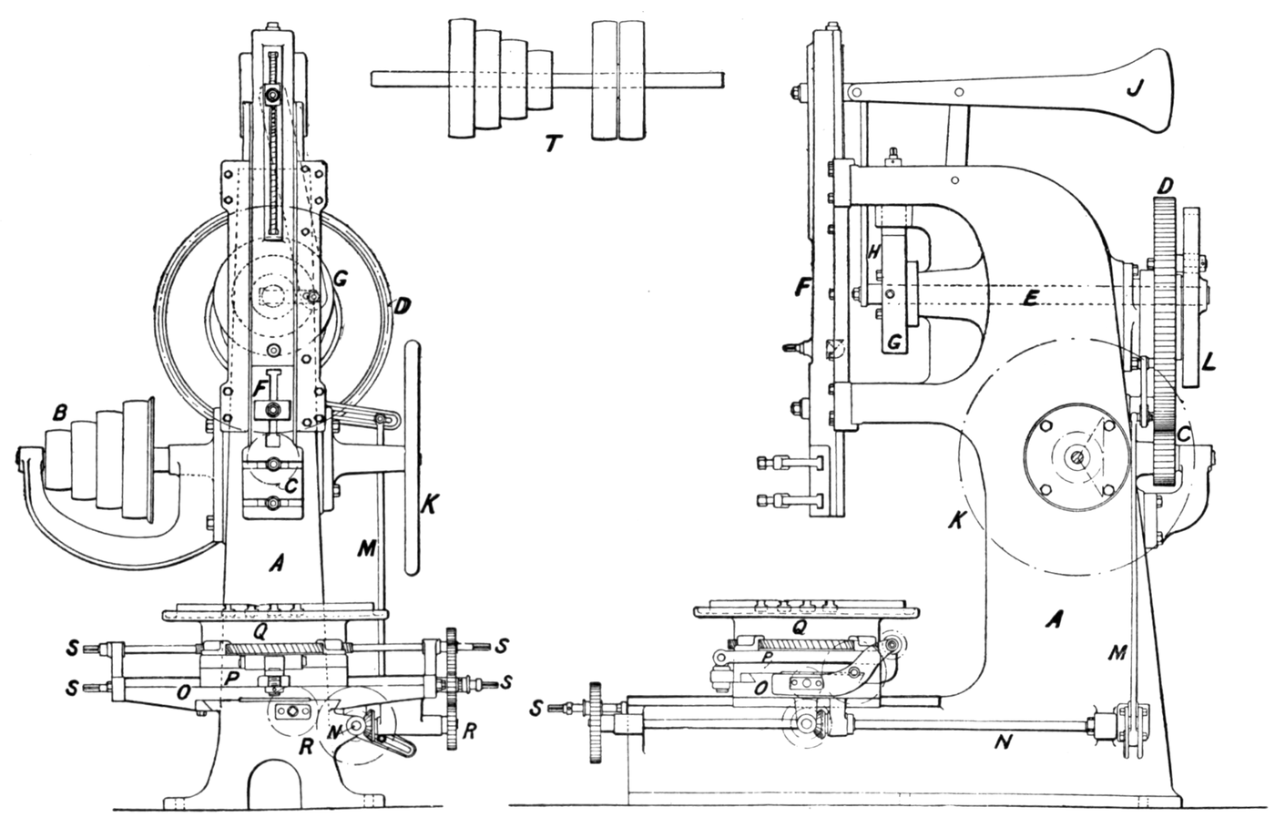


Whitworth Quick-Return Mechanism
Maagizo
Lay out the two centres — the offset IS the mechanism
Lay out the two centres — the offset IS the mechanism
Two rotation centres, deliberately not concentric. Everything follows from their spacing.
- Cut a baseplate 350 × 250 mm from 18 mm Baltic birch plywood.
- Mark centre A (the driving crank) on a vertical centreline, 120 mm from the bottom edge.
- Mark centre B (the slotted link pivot) on the same line, 45 mm BELOW A.
- Centre-punch both, and write the 45 mm offset on the board.
Modern build spec (derived). A 45 mm offset with a 70 mm crank radius gives roughly a 2:1 stroke-time ratio — fast enough to be obvious when you measure it in step 5, without the extreme link angles that make a model bind. Whitworth's own machines were proportioned for the cut, not for demonstration.
Get these two centres right and the mechanism works. Everything else is ordinary bar and pivot work; this one dimension is what makes it a quick-return rather than a slow crank.Vifaa kwa hatua hii:
 Mbao ya tabaka ya mbetula ya Baltiki1 karatasi
Zana zinazohitajika:
 Msumeno wa Kupinda
 Skwea ya mchanganyiko
 Kigwe cha Katikati
 Kipima-unene cha dijitali cha inchi 6
Make the slotted link
Make the slotted link
A long bar with a slot down most of its length, pivoting at B.
- Cut a link 260 × 40 mm from 6 mm aluminium flat bar.
- Drill the pivot hole at one end, 8.0 mm, to take a 608 bearing pressed into a plywood boss at B.
- Mark a slot on the centreline running from 40 mm above the pivot to 30 mm from the far end.
- Drill 10 mm holes at each slot end and join them with the coping saw.
- File both slot faces straight and parallel to a sliding fit on your crank-pin bearing.
Vifaa kwa hatua hii:
 Ubao bapa wa alumini1 kipande
 Fani ya Mipira2 vipande
Zana zinazohitajika:
 Fremu ya msumeno wa chuma na mabapa
 Msumeno wa kukata mikunjo
 Kekee cha Betri
 Seti ya vichimbuzi
 Seti ya tupa
 Kibano cha meza ya kaziKipima-unene cha dijitali cha inchi 6
Build the driving crank and its pin
Build the driving crank and its pin
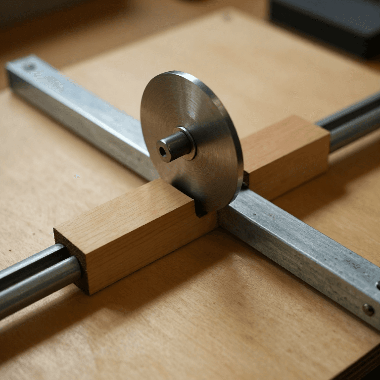
The crank turns about A; its pin rides in the slot of the link that pivots about B.
- Cut a 160 mm disc from 18 mm ply and bore its centre 22 mm for a 608 bearing at A.
- Drill the pin hole 70 mm from the disc centre, 5.0 mm.
- Fit an M5 × 35 socket head cap screw as the crank pin with M5 flat washer × 2 and M5 hex nut × 1 behind.
- Run a second 608 bearing on the pin so the slot sees a rolling outer race.
- Mount the disc at A with an M5 × 40 socket head cap screw through the bearing.
What Whitworth's machines used: a cast iron bull wheel with an adjustable crank pin in a radial T-slot, so the stroke could be reset for each job. Modern build spec (derived): a single fixed pin hole here for simplicity — drill a second hole at 50 mm if you want to demonstrate that changing the crank radius changes the STROKE while leaving the time ratio alone.
That last point is the one people get wrong: crank radius sets stroke LENGTH, the A-to-B offset sets the return RATIO. They are independent, and having both holes lets you prove it.Vifaa kwa hatua hii:
Mbao ya tabaka ya mbetula ya Baltiki1 karatasi Washa bapa4 vipande
 Nati ya pembe sita2 vipandeFani ya Mipira2 vipande
Zana zinazohitajika:
Kekee cha BetriSeti ya vichimbuziMsumeno wa kukata mikunjo Seti ya funguo za pembe sitaKipima-unene cha dijitali cha inchi 6
Add the connecting rod and ram, in this order
Add the connecting rod and ram, in this order
The link's far end drives a ram sliding in guides. Assembly order is forced by access.
- Cut two guide rails 220 × 25 mm from 6 mm aluminium flat bar, and a ram 200 × 30 mm.
- Clamp the rails in place and drill through rail and baseplate together at 4.2 mm, four holes per rail; countersink underneath.
- Fit the crank at A and the slotted link at B FIRST — both are inaccessible once the rails are on.
- Cut a connecting rod 110 mm between hole centres and pivot it to the link's far end with an M4 × 20 socket head cap screw, M4 flat washer × 2, M4 nylon insert lock nut × 1.
- Pivot the rod's other end to the ram the same way.
- Fix the rails with M4 × 25 socket head cap screws × 8, M4 flat washers × 16, M4 nylon insert lock nuts × 8, setting clearance with a sheet of paper before final tightening.
Vifaa kwa hatua hii:
Ubao bapa wa alumini2 vipande Skrubu Yenye Kichwa cha Soketi10 vipandeWasha bapa20 vipande
 Nati ya Kufungasha yenye Nailoni10 vipande
Zana zinazohitajika:
Kekee cha BetriSeti ya vichimbuzi Seti ya Ncha za Kupanua MatunduSeti ya funguo za pembe sitaFremu ya msumeno wa chuma na mabapaSkwea ya mchanganyiko
Measure the ratio, and history
Measure the ratio, and history
Measure the asymmetry rather than believing it.
- Mark the crank rim every 15 degrees.
- Note the crank angle at which the ram reaches each end of its travel.
- Count the degrees spent on the cutting stroke and on the return.
- Divide. With a 45 mm offset and 70 mm crank you should find roughly 2:1.
- Now move the crank pin to the 50 mm hole and repeat — the stroke shortens, the RATIO does not change.
The mechanism is not making the machine faster overall; it is reallocating one revolution between useful work and wasted travel. Cutting speed stays whatever the shaft speed dictates.
History. Sir Joseph Whitworth (1803-1887) built this into his shaping machines from the 1840s. He is better known in this catalogue for the Whitworth screw thread, the first national standard fastener thread — and the two achievements come from the same instinct, which is that precision and repeatability are worth engineering for deliberately rather than hoping for.
Why it mattered commercially: a shaper's output is strokes per hour. Cutting the return time roughly in half raises output by a large fraction with no extra power, no extra floor space and no extra operator skill. That is an unusually clean win, and it is why the mechanism spread through shapers, slotters and planers.
Its siblings and the trade: the crank and slotted link here produces a fast return but a cutting stroke whose speed VARIES through the stroke, which affects surface finish. The Scotch yoke gives pure sinusoidal motion with equal times each way. A crank and connecting rod gives a mild asymmetry for free. Each is a different distribution of one revolution, and the right choice depends on whether you care most about time, about constant cutting speed, or about wear.
Zana zinazohitajika:
Kipima-unene cha dijitali cha inchi 6Skwea ya mchanganyikoVifaa
8- 1 karatasiKishikilia Nafasi
- 3 vipandeKishikilia Nafasi
- Kishikilia Nafasi
- 4 vipandeKishikilia Nafasi
- 2 vipandeKishikilia Nafasi
- 10 vipandeKishikilia Nafasi
- 20 vipandeKishikilia Nafasi
- 10 vipandeKishikilia Nafasi
Zana Zinazohitajika
12- 1 vendor sell this, none ship to you yetKishikilia Nafasi
- Kishikilia Nafasi
- Kishikilia Nafasi
- Kishikilia Nafasi
- Kishikilia Nafasi
- Kishikilia Nafasi
- 1 vendor sell this, none ship to you yetKishikilia Nafasi
- Kishikilia Nafasi
- Kishikilia Nafasi
- Kishikilia Nafasi
- Kishikilia Nafasi
- Kishikilia Nafasi
Blueprint zinazohusiana
Blueprint hizi zinashiriki maarifa — mbinu, vifaa au kanuni

CC0 Umma Wote
Mchoro huu umetolewa chini ya CC0. Uko huru kunakili, kubadilisha, kusambaza, na kutumia kazi hii kwa madhumuni yoyote, bila kuomba ruhusa.
Saidia Mtengenezaji kwa kununua bidhaa kupitia Mchoro wao ambapo wanapata Kamisheni ya Mtengenezaji iliyowekwa na Wachuuzi, au unda marudio mapya ya Mchoro huu na uiunganishe kama kiungo katika Mchoro wako kuchangia mapato.