협업
예술
뷰티 및 웰니스
공예
문화 및 역사
엔터테인먼트
환경
음식 및 음료
역공학
과학
스포츠
기술
웨어러블
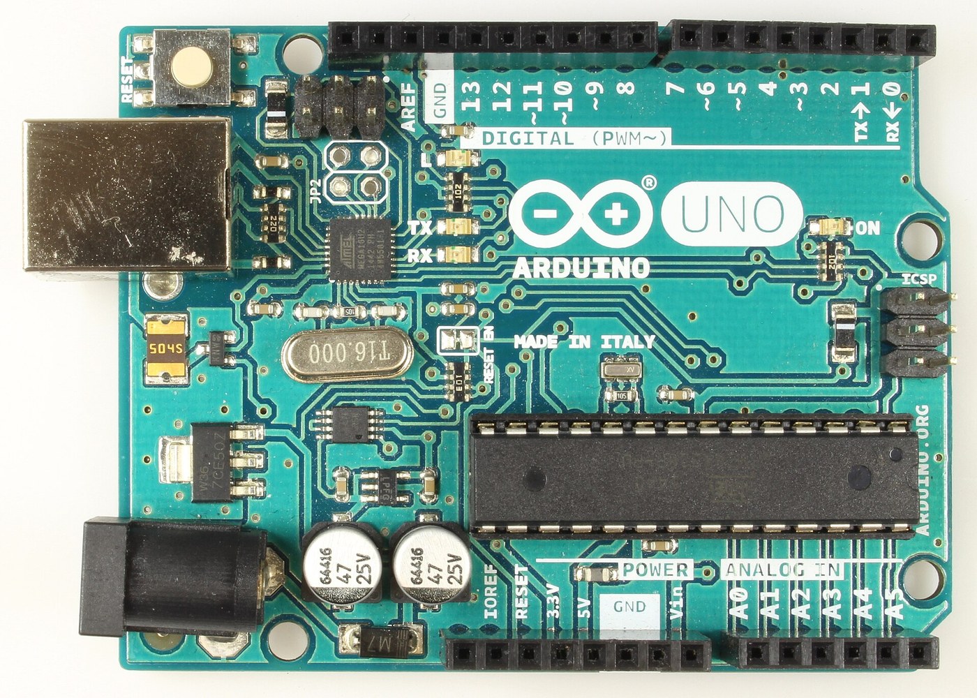


Arduino Uno R3: Assembled from Arduino's Open UNO-TH Rev3e Design Files and Flashed over ICSP
The Arduino Uno R3 is open hardware: Arduino publishes its schematic and board layout. This blueprint builds one from those files, part by part, then loads the firmware into its two processors.
Result: an Arduino Uno R3. An ATmega328P (16 MHz, 32 kB flash, 2 kB SRAM, 1 kB EEPROM) runs your programs; an ATmega16U2 turns USB into its serial link. It runs from USB (5.5 V at most) or 6-20 V at the DC jack.
Source: Arduino UNO-TH_Rev3e design files and the A000066 schematic and datasheet (Arduino, CC BY-SA). Unknown: how every bought part is made; no public source in hand says. The soldering method is ours. Picture: Wikimedia Commons.
고급
1 day
안내
1
1
Get the bare board
Get the bare board
Have the two-layer board made to Arduino's UNO-TH_Rev3e board layout (the .brd file of the design files). Check it against the schematic before fitting anything.
이 단계의 재료:
 인쇄 회로 기판1 UNO-TH Rev3e layout
필요한 도구:
 확대 루페
2
2
Fit the small surface-mount parts
Fit the small surface-mount parts
Solder the chip parts to their marked places: resistor arrays RN1 (10K), RN2 and RN4 (1K), RN3 (22R); R1, R2 (1M); capacitors C1, C2, C4-C7, C10 (100n), C3, C8 (1u), C9, C11 (22p); varistors Z1, Z2; ferrite bead L1; inductor L2 (10 uH); diodes D2, D3; LEDs ON (green), L, RX, TX (yellow). Ours: flux, tweezers and hot air or a fine iron, checked under a loupe.
이 단계의 재료:
 칩 저항 어레이4 RN1-RN4
 칩 저항2 1M
 세라믹 칩 커패시터11 7x100n, 2x1u, 2x22p
 칩 배리스터2 Z1, Z2
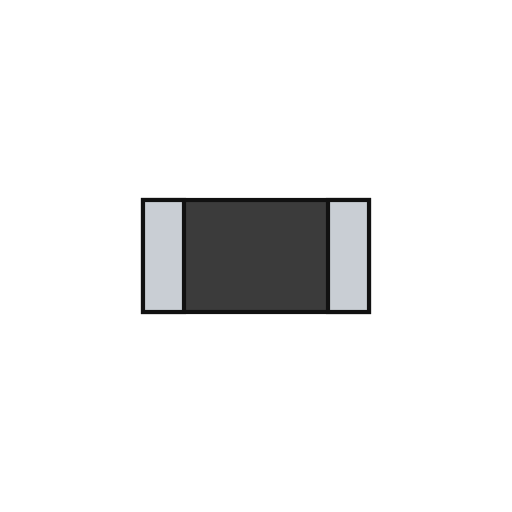 페라이트 비드1 L1
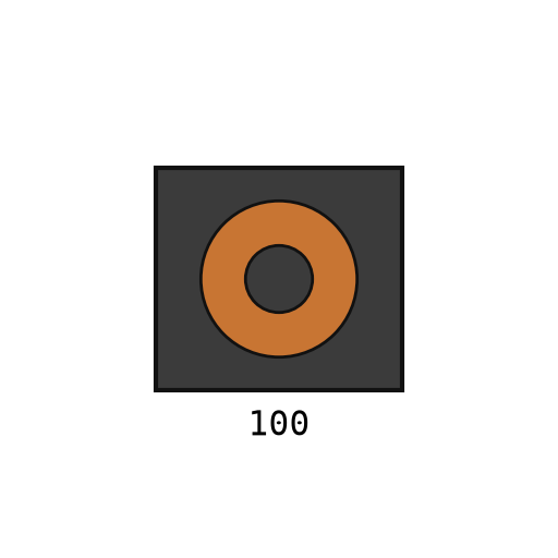 표면 실장 인덕터1 L2
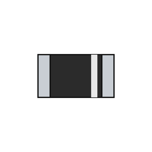 표면 실장 다이오드2 D2, D3
 칩 LED4 1 green, 3 yellow
 땜납 선1 a little
필요한 도구:
 플럭스
 끝이 뾰족한 핀셋
 열풍 리워크 스테이션
 인두확대 루페
3
3
Fit the power and chip parts
Fit the power and chip parts
Solder the ATmega16U2 (U3), the 16 MHz resonator Y2 and crystal Y1, the 5 V regulator NCP1117 (U1) and 3.3 V regulator LP2985 (U2), the LMV358 op-amp (U5), the FDN340P transistor (T1), the M7 diode (D1), the 500 mA resettable fuse (F1) and the 47 uF capacitors PC1, PC2 with their polarity as marked.
이 단계의 재료:
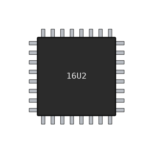 ATmega16U2 마이크로컨트롤러1 U3
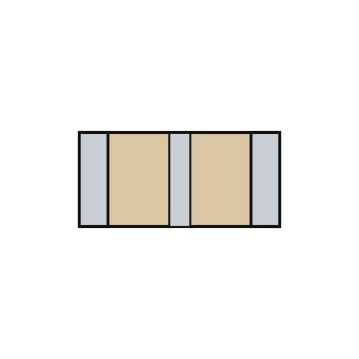 압전 세라믹 공진자1 Y2
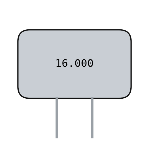 수정 진동자1 Y1
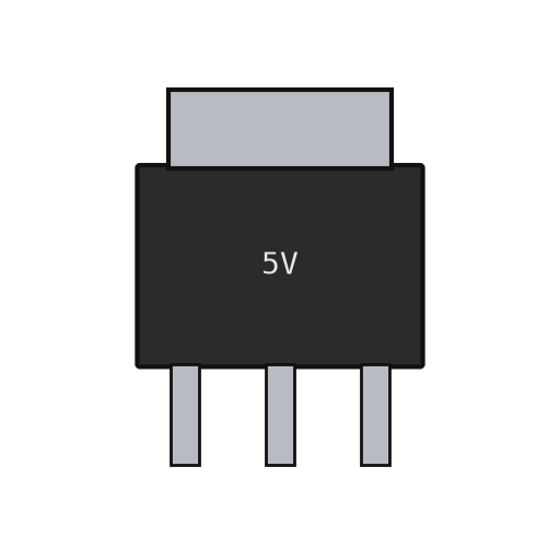 선형 전압 레귤레이터2 U1 5 V, U2 3.3 V
 연산 증폭기 IC1 U5 LMV358
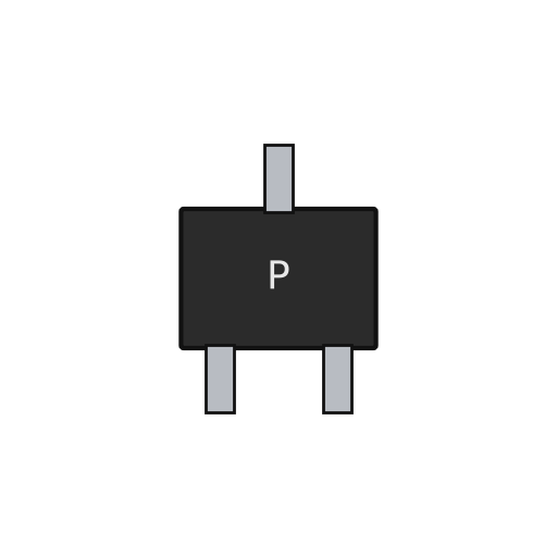 P채널 MOSFET1 T1표면 실장 다이오드1 D1 M7
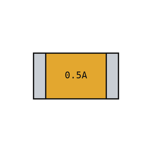 리셋형 퓨즈1 F1
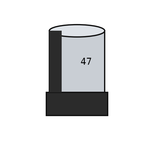 극성 칩 커패시터2 PC1, PC2땜납 선1 a little
필요한 도구:
플럭스끝이 뾰족한 핀셋열풍 리워크 스테이션인두확대 루페4
4
Fit the through-hole parts
Fit the through-hole parts
Solder the USB-B socket (X2), the DC jack (X1), the reset switch, the female headers (one 10-way, two 8-way, one 6-way) and the two 2x3 ICSP headers. Seat the ATmega328P in its place (ZU4).
이 단계의 재료:
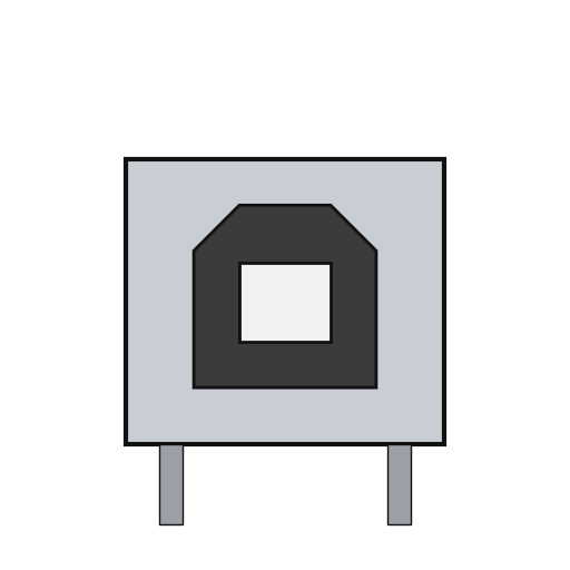 USB-B 소켓1 X2
 DC 배럴 잭1 X1
 푸시 버튼1 RESET
 핀 헤더6 10x1, 2x 8x1, 6x1 female; 2x 3x2 ICSP
 ATmega328P 마이크로컨트롤러1 ZU4땜납 선1 as needed
필요한 도구:
인두5
5
Flash and check
Flash and check
Check with a meter that 5 V and GND are not shorted. Through the ICSP headers, load the USB-to-serial firmware into the ATmega16U2 and the bootloader into the ATmega328P. Plug in USB: the green ON LED lights, and the blink test in the next step flashes the L LED. Ours: an AVR ISP programmer and a multimeter.
이 단계의 재료:
 Arduino Uno 펌웨어1 download
필요한 도구:
 멀티미터
 AVR ISP 프로그래머
 USB-B 케이블
6
6
The blink test
The blink test
blink_test.ino: the same check as Arduino's Blink example. Upload it over USB from the Arduino IDE with the board set to Arduino Uno; the L LED on pin 13 turns on for one second and off for one second, over and over. If it does, both processors, the USB link and the bootloader work.
blink_test.inocpp
필요한 도구:
USB-B 케이블재료
24- 1 UNO-TH Rev3e layout플레이스홀더
- 4 RN1-RN4플레이스홀더
- 2 1M플레이스홀더
- 11 7x100n, 2x1u, 2x22p플레이스홀더
- 2 Z1, Z2플레이스홀더
- 1 L1플레이스홀더
- 1 L2플레이스홀더
- 1 D1 M7플레이스홀더
- 4 1 green, 3 yellow플레이스홀더
- 1 as needed플레이스홀더
- 플레이스홀더
- 1 Y2플레이스홀더
- 1 Y1플레이스홀더
- 2 U1 5 V, U2 3.3 V플레이스홀더
- 1 U5 LMV358플레이스홀더
- 1 T1플레이스홀더
- 1 F1플레이스홀더
- 2 PC1, PC2플레이스홀더
- 1 X2플레이스홀더
- 플레이스홀더
- 플레이스홀더
- 플레이스홀더
- 1 ZU4플레이스홀더
- 1 download플레이스홀더
이 블루프린트로 만드는 것
관련 블루프린트
이 블루프린트들은 지식을 공유합니다 — 기술, 재료 또는 원리
CC0 퍼블릭 도메인
이 블루프린트는 CC0로 공개되었습니다. 어떤 목적으로든 자유롭게 복사, 수정, 배포 및 사용할 수 있습니다.
제품 구매를 통해 메이커를 지원하세요. 판매자가 설정한 메이커 커미션 을 받거나, 이 블루프린트의 새로운 반복을 만들어 연결로 포함시킬 수 있습니다.