예술
뷰티 및 웰니스
공예
문화 및 역사
엔터테인먼트
환경
음식 및 음료
역공학
과학
스포츠
기술
웨어러블
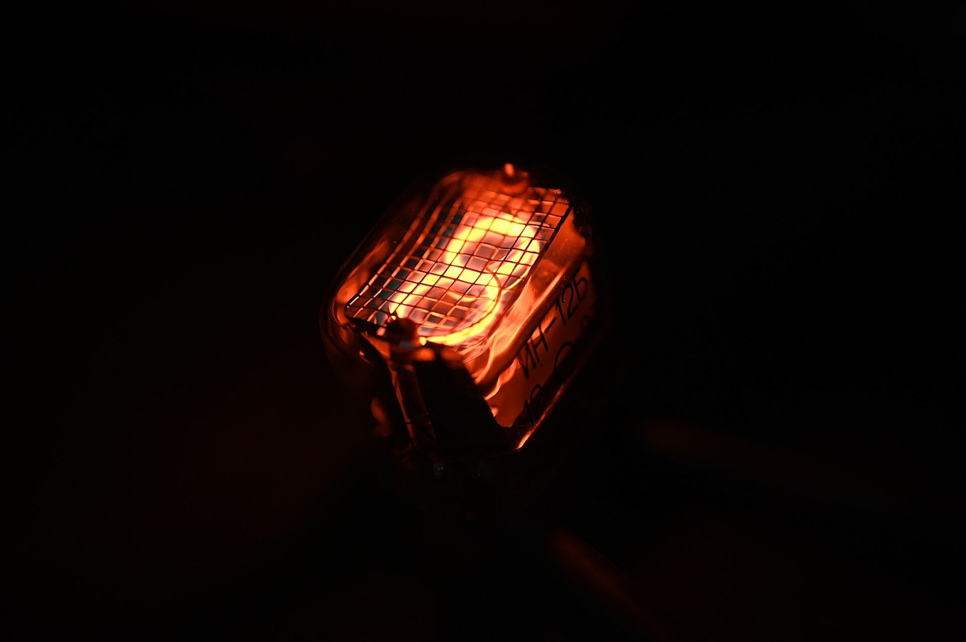


The Nixie Tube
Before a digit could be assembled from segments, somebody had to decide it was acceptable to assemble it at all. The Nixie's answer was that it was not: if you want to display a five, put a five in the tube, shaped out of wire, and make it glow.
Haydu Brothers Laboratories built the first ones and Burroughs bought the company and the design in 1955, trademarking the name from their internal designation NIX I — Numeric Indicator eXperimental number one. Inside a glass envelope filled with neon at low pressure sit ten cathodes, each bent into the shape of one digit, stacked one behind another like pages in a book. A wire mesh anode surrounds them. Pull one cathode down towards ground and a glow discharge forms on it and only on it, wrapping the wire in the orange light of excited neon.
The result is a real numeral, with real depth, in a colour nothing else quite makes. It is also a cold-cathode gas discharge device operating at a hundred and seventy volts in an era of five-volt logic, which is the whole story of its life and its death.
This blueprint drives one properly, which means understanding three things that will otherwise destroy either the tube or the microcontroller: why the anode resistor is structural rather than protective, why the transistor's voltage rating is the only specification that matters, and why a Nixie that displays the same digit for six months will never display the others again.
The sibling blueprint is the seven-segment LED display, which does the same job for two volts and a tenth of the cost and looks like a calculator. Both are in this batch. The comparison is in the last step and it is not as one-sided as it sounds.
HIGH VOLTAGE. 170 V DC will hurt you and can kill you across the chest. Read the safety notes in step 2 and build it on an insulated bench with one hand behind your back.
중급
5 hours
안내
1
1
A glow discharge that happens to be shaped like a five
A glow discharge that happens to be shaped like a five
The neon tube blueprint this one links back to covers the discharge itself: raise the field across a low-pressure gas until stray electrons gain enough energy between collisions to ionise neon atoms, and you get an avalanche, a self-sustaining plasma, and light at the neon lines around 585 to 640 nm. That is the orange.
A NIXIE ADDS TWO IDEAS to that.
THE FIRST is that a glow discharge in the normal-glow regime clings to the cathode. The negative glow forms as a sheath a fraction of a millimetre off the cathode surface and follows its shape exactly, however complicated that shape is. Bend a wire into a figure five and the glow is a figure five. Nobody has to focus or steer anything; the discharge does the work because that is where the field is strongest.
THE SECOND is that the normal glow has a remarkable property: over a wide current range, the voltage across the tube does not change. What changes is the AREA of cathode that is covered. Double the current and the glow simply spreads over twice as much wire at the same voltage. That is why a Nixie looks fully lit rather than dim at low current — until you drop below the current needed to cover the whole digit, at which point part of the numeral goes dark and it looks broken rather than dim.
THE GAS is neon with a small amount of argon or mercury, and this is not a detail. A Penning mixture — a trace of a gas whose ionisation energy sits below the metastable energy of the majority gas — lowers the striking voltage substantially, because a metastable neon atom that bumps into an argon atom ionises it for free. Without it a Nixie would need well over 200 V to strike. With it, 170 will do.
THE NUMBERS you are going to work with, for a typical Soviet IN-12 or IN-14, which is what is actually available now:
striking voltage about 170 V, and it must be exceeded to start
maintaining voltage about 140 V once it is running
operating current 2.0 to 2.5 mA per digit, and 3.5 mA is the absolute maximum
digit height 18 mm on an IN-12, 40 mm on the large IN-18
THE GAP BETWEEN 170 AND 140 IS THE ENTIRE DESIGN PROBLEM. A device that needs more voltage to start than to run has a NEGATIVE RESISTANCE region: once it strikes, the voltage across it falls, so the current through it rises, so the voltage falls further. There is nothing in the tube to stop this. The current is limited by the external resistor and by nothing else, and if you forget it the tube destroys its own cathode in seconds.
This is the same reason a fluorescent lamp needs a ballast and a neon sign needs a transformer with deliberately poor regulation. It is a property of gas discharges, not a fault in this particular tube.
이 단계의 재료:
 닉시관(IN-12)1 개
2
2
The driver, and the transistor rating that matters
The driver, and the transistor rating that matters
One anode resistor, ten cathode switches. That is the entire circuit and the schematic shows one of the ten.
R1 IS STRUCTURAL. It sets the current, because as step 1 explained, the tube will not. Size it from the supply and the maintaining voltage, not the striking voltage: with 180 V in and about 140 V across a running tube, R1 drops 40 V, and for 2 mA that is 20 kilohms. Use 22k as the nearest standard value and give it a 2 W rating even though it only dissipates 0.08 W in normal use, because if a cathode driver fails short the resistor is the only thing between the supply and ground.
CHECK THE SUPPLY ARITHMETIC BEFORE POWERING ANYTHING. The supply must exceed the STRIKING voltage with the resistor in circuit, or the tube will simply never light. 180 V supply, 170 V to strike, leaves 10 V across a 22k resistor, which is 0.45 mA — enough to start the avalanche, and once it starts the voltage collapses to 140 and the current rises to the 2 mA you designed for. If you use a 160 V supply the tube stays dark for ever and looks dead. This catches people constantly.
Q0 IS WHERE PEOPLE DESTROY THINGS. When the digit is off, the transistor's collector sits at the full supply voltage. An MPSA42 is rated 300 V collector-emitter and is the standard part for this. A 2N3904 is rated 40 V. It will not merely fail to work; a shorted transistor puts the entire high-voltage rail directly onto your microcontroller pin and takes the board with it. There is one specification that matters here and it is Vceo. Check it on the actual part in your hand.
R2 limits base current. 10k from a 3.3 V GPIO gives about 0.25 mA of base drive, and with an MPSA42's minimum gain of 40 at these currents that supports 10 mA of collector current — five times what the tube draws. Comfortable.
WIRE ALL TEN CATHODES THE SAME WAY. The classic part is the 74141, or its far more available Soviet equivalent the K155ID1: four BCD inputs, ten open high-voltage outputs, one package, and it will not assert two outputs at once. If you use discrete transistors instead, you must enforce that in software, because two cathodes pulled low at once does not display two digits. The discharge picks whichever strikes first and the other cathode just sits there being sputtered.
SAFETY, and this is the step where it applies. 170 V DC across the chest can stop a heart. Build on an insulated surface. Keep one hand in your pocket while probing. Put a bleeder resistor of 220k across the high-voltage rail so the reservoir capacitor discharges in a few seconds instead of sitting there charged, and check with a meter that it actually has before you touch anything. Boost modules for Nixie work are readily sold and are the sane choice over building the converter yourself.
KiCanvas 뷰어 로딩 중...
전문 PCB 디자인 뷰어
이 단계의 재료:
닉시관(IN-12)1 개 고전압 트랜지스터(MPSA42)10 개
 고전압 승압 모듈1 개
 저항 키트1 키트
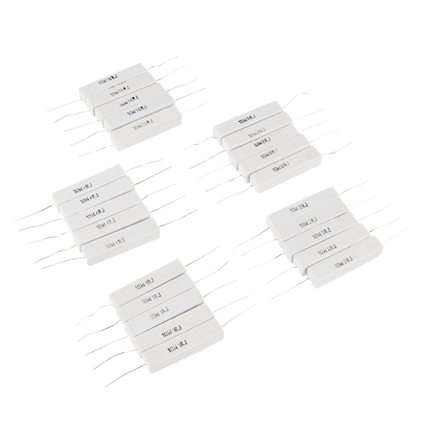 Power Resistor Kit - 10W (25 pack)1 키트
필요한 도구:
 실험실급 디지털 멀티미터
 납땜 스테이션
 Breadboard
3
3
Measure the strike, the maintain, and the negative resistance
Measure the strike, the maintain, and the negative resistance
Jupyter 노트북 불러오는 중…
필요한 도구:
실험실급 디지털 멀티미터 직류 전원 공급기
 데스크톱 컴퓨터
4
4
Cathode poisoning, and the anti-poisoning routine
Cathode poisoning, and the anti-poisoning routine
A Nixie that spends its life showing a clock has a problem. The hours digit displays a 1 for a third of the day; the tens-of-minutes digit never shows 6 through 9 at all. After a year the unused cathodes will not light properly, and the damage is not reversible by wishing.
WHAT IS HAPPENING. Ion bombardment sputters metal off whichever cathode is lit and it lands on the neighbours. The deposited film has a higher work function than the clean nickel underneath, so a coated cathode needs more voltage to strike, and eventually it strikes only in patches or refuses entirely. The lit digit is fine. The dark ones are being slowly buried by it.
There is a second version of the same problem running the other way: a cathode that is never used accumulates contamination from the getter and the glass and develops dark blotches. Both are called cathode poisoning and both have the same cure — run every cathode, hard, regularly.
THE ANTI-POISONING ROUTINE. Cycle every digit at slightly above normal current for a few minutes, periodically. Every Nixie clock built since people rediscovered these tubes runs one, typically for a couple of minutes an hour or a longer sweep once a day. Mild poisoning is genuinely reversible this way; the sputtered film is thin and running the cathode hot re-sputters it off. Advanced poisoning is not.
The sketch below does three things. It multiplexes the tube so you can see a digit at all; it runs a scheduled anti-poisoning sweep; and it measures something worth measuring — the strike delay of each cathode, which is a direct indicator of how poisoned that cathode is. A clean cathode strikes within a few hundred microseconds of the drive going low. A poisoned one takes milliseconds, or needs several attempts. Logging that number for all ten digits gives you a health check on a tube before you spend money on it.
A NOTE ON MULTIPLEXING. Nixies can be multiplexed across several tubes by switching the ANODES and sharing one set of cathode drivers, and commercial clocks did exactly this to save nine transistors per tube. Do not multiplex faster than about 1 kHz per tube: the discharge takes real time to strike and to extinguish, and above that you spend most of the period in transitions and the tube dims and the digits ghost into each other.
nixie.inocpp
이 단계의 재료:
닉시관(IN-12)1 개고전압 트랜지스터(MPSA42)10 개필요한 도구:
 ESP32 개발 보드
 오실로스코프
 점퍼 와이어 세트
재료
5- 1 개플레이스홀더
- 플레이스홀더
- 1 개플레이스홀더
- 플레이스홀더
- 1 키트₩76
필요 도구
8- 플레이스홀더
- 플레이스홀더
- Breadboard - Classic10% 수수료₩127
- 플레이스홀더
- 플레이스홀더
- 플레이스홀더
- 플레이스홀더
- 플레이스홀더
예상 총액
만든 사람이 산 것. 가격이 없는 재료는 구매하는 곳에서 구하면 됩니다.
관련 블루프린트
이 블루프린트들은 지식을 공유합니다 — 기술, 재료 또는 원리




CC0 퍼블릭 도메인
이 블루프린트는 CC0로 공개되었습니다. 어떤 목적으로든 자유롭게 복사, 수정, 배포 및 사용할 수 있습니다.
제품 구매를 통해 메이커를 지원하세요. 판매자가 설정한 메이커 커미션 을 받거나, 이 블루프린트의 새로운 반복을 만들어 연결로 포함시킬 수 있습니다.