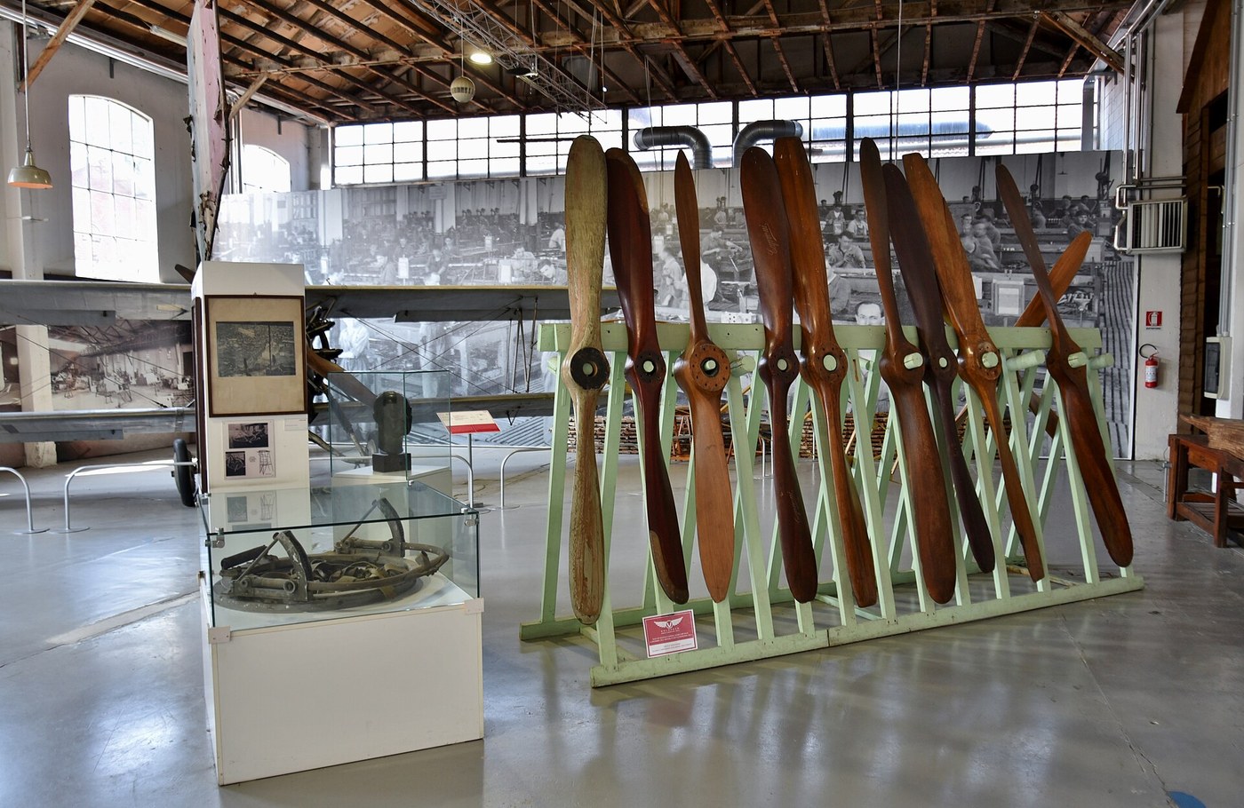


The Propeller as a Rotating Wing
안내
Show that a blade section is just a wing
Show that a blade section is just a wing
Prove the analogy before relying on it.
- Cut a short section of aerofoil identical to your best wind-tunnel result.
- Mount it in the tunnel and record lift and drag at a few angles, as before.
- Now reason about what that same section experiences when it is instead sweeping a circle at radius r and turning at n revolutions per second.
- Work out the speed it meets the air: the vector sum of the aircraft’s forward speed and the rotational speed 2πrn.
The section does not know or care whether it is flying straight or going round in a circle — it only experiences a relative wind and an angle to it. That is the whole insight. Lift becomes thrust because the section is oriented so its lift points forward; drag becomes the torque the engine must overcome.
The vector sum is why a propeller behaves so differently standing still and at speed. On the ground the forward component is zero and the blade meets the air at a very coarse angle — often past the stall. This is exactly why a fixed-pitch propeller optimised for cruise gives poor static thrust, and it is the problem the variable-pitch blueprint later solves.이 단계의 재료:
 바스우드 판1 장
 모눈종이1 pad
필요한 도구:
 탁상 밴드 톱
 벨트 샌더
벨트 샌더 디지털 캘리퍼스 6인치
 각도기
각도기 스프링 저울
 투명 보안경
Calculate the twist the blade must have
Calculate the twist the blade must have
Do the arithmetic that produces the shape, so the shape stops being mysterious.
- Choose a design forward speed V and a rotational speed n.
- Divide the blade into stations at, say, 25, 50, 75 and 100 percent of the radius.
- At each station compute the rotational speed 2πrn and the resulting helix angle, whose tangent is V divided by that rotational speed.
- Add your aerofoil’s best angle of attack to the helix angle at each station. That sum is the blade angle there.
- Tabulate the four blade angles.
The angles fall steeply from root to tip — often from around 40° near the hub to under 15° at the tip. The blade is not bent for strength or elegance; each station is individually aimed so it meets the air at the angle the tunnel said was best.
Notice what happens at the very centre: the helix angle tends toward 90° and the blade would have to stand almost edge-on to the disc. That region produces almost no useful thrust, which is why propeller roots are usually blended into a spinner or simply thickened for strength — the aerodynamics there are a lost cause and the structure needs the material.이 단계의 재료:
모눈종이1 pad필요한 도구:
각도기디지털 캘리퍼스 6인치 조합 직각자
Carve the blade to the calculated angles
Carve the blade to the calculated angles
Cut the numbers into wood, one station at a time.
- Start from a rectangular hardwood blank of the right length and thickness, with the centreline marked on all four faces.
- Mark the four stations across the blank.
- At each station, cut a gauge from card at the calculated blade angle.
- Carve down to each gauge in turn, working from tip to root, then fair the surface smoothly between stations.
- Shape the aerofoil section on each blade face, thicker at the root and thinner toward the tip.
Fairing between the stations is where a propeller is made or ruined. The four gauges only fix four sections; the surface between them must run smoothly, because any local bump or hollow produces flow separation and both loses thrust and makes noise.
The Wrights carved theirs from laminated spruce with a hatchet and a drawknife, and achieved around 66 percent efficiency at a time when the best marine screws managed roughly 50. Their advantage was not their carving, it was that they had a tunnel and could aim each station at a number.이 단계의 재료:
 집성 가문비나무 소재1 개
 목공용 접착제1 병
 사포1 팩사포1 팩
필요한 도구:
탁상 밴드 톱벨트 샌더 줄 세트디지털 캘리퍼스 6인치각도기
 C형 클램프
 바이스(만력)투명 보안경
Balance it, and understand why that is not optional
Balance it, and understand why that is not optional
An unbalanced propeller is a vibration source bolted to the front of the machine.
- Mount the finished propeller on a free-running horizontal spindle with very low friction.
- Let it settle. If one blade consistently swings to the bottom, that blade is heavy.
- Remove material from the heavy blade’s FACE — never from its edges or tip profile — or add weight at the light blade’s root.
- Repeat until it shows no preferred resting position.
- Also check horizontal balance: the blades must weigh the same at the same radius, not merely weigh the same.
An out-of-balance propeller applies a rotating force at the shaft frequency, which fatigues the mounting, blurs instruments and cracks structure over time. The mass involved may be a gram; the force scales with the square of the rotational speed, so a gram at 3000 rpm is not a small thing.
Never correct balance by shortening a blade. Different radii mean different tip speeds, different thrust and a bending moment that alternates once per revolution — you would trade a vibration you can measure for a fatigue crack you cannot see.이 단계의 재료:
사포1 팩필요한 도구:
 디지털 저울디지털 캘리퍼스 6인치줄 세트
 디지털 각도계투명 보안경
Measure thrust and efficiency, and find the tip-speed wall
Measure thrust and efficiency, and find the tip-speed wall
Now find out whether the calculation was worth doing.
- Mount the propeller on a motor fixed to a pivoted arm, with a spring scale reading the thrust it produces.
- Measure thrust and rotational speed together across a range of speeds, along with the electrical power going in.
- Compute thrust per watt at each speed.
- Now compute the TIP speed at each: 2πRn.
Thrust per watt improves with speed and then falls away, and the fall begins as tip speed climbs toward the speed of sound. As the tip approaches roughly 0.85 to 0.9 of sonic speed, local flow over the blade goes supersonic, shock waves form, drag rises steeply and efficiency collapses — and the propeller gets very loud, because that noise is the energy you are no longer converting to thrust.
This is the hard ceiling on propeller-driven flight, and it is the reason the batch ends where it does. You cannot spin faster and you cannot usefully make the blade longer, because a longer blade has a faster tip at the same rpm. The propeller runs out of road at somewhere around 700 km/h, and the only way past is to stop using one.
That is the argument for the turbojet, and it is a genuine limit rather than a failure of imagination. Propellers remain the most efficient thing available below their ceiling, which is exactly why turboprops still dominate short regional routes today.이 단계의 재료:
모눈종이1 pad 브러시 없는 모터1 세트
 전자식 속도 제어기1 세트
필요한 도구:
스프링 저울 디지털 회전 속도계디지털 저울디지털 캘리퍼스 6인치
 고속 촬영이 되는 스마트폰투명 보안경
재료
8- 1 장플레이스홀더
- 1 pad플레이스홀더
- 1 개플레이스홀더
- 1 병플레이스홀더
- 1 팩플레이스홀더
- 1 팩플레이스홀더
- 1 세트플레이스홀더
- 플레이스홀더
관련 블루프린트
이 블루프린트들은 지식을 공유합니다 — 기술, 재료 또는 원리


CC0 퍼블릭 도메인
이 블루프린트는 CC0로 공개되었습니다. 어떤 목적으로든 자유롭게 복사, 수정, 배포 및 사용할 수 있습니다.
제품 구매를 통해 메이커를 지원하세요. 판매자가 설정한 메이커 커미션 을 받거나, 이 블루프린트의 새로운 반복을 만들어 연결로 포함시킬 수 있습니다.